General scsi cable-routing guidelines, Scsi a and b backplane connections, Optional internal tape drive connections – Dell PowerEdge 2850 User Manual
Page 11
General SCSI Cable-Routing Guidelines
This section provides general guidelines about how to properly route SCSI cables inside the system.
SCSI A and B Backplane Connections
riser board.
Proper SCSI cable-routing guidelines for this configuration are listed below:
l
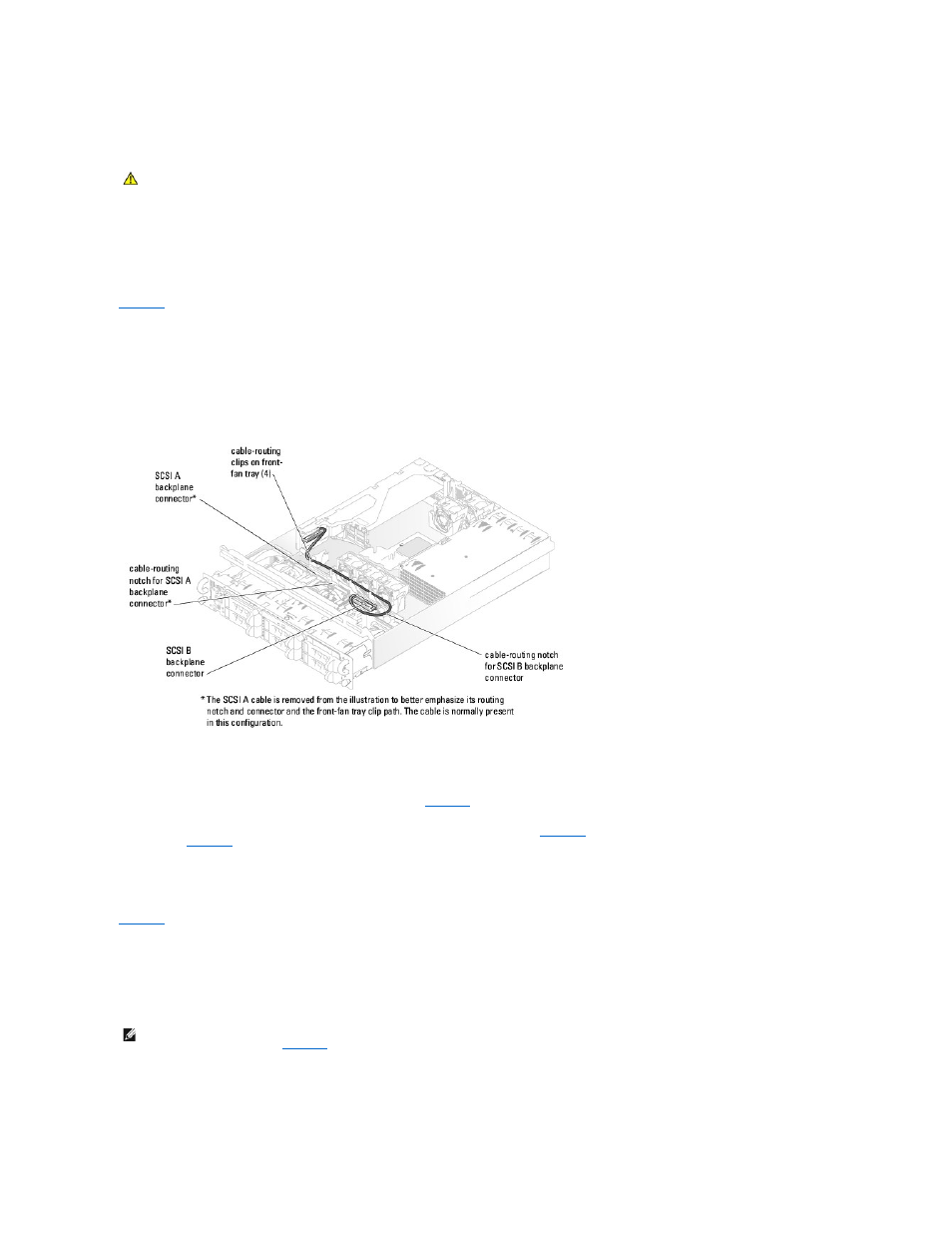
When you attach a cable to either the SCSI A or B backplane connector, ensure that the cable is placed in the respective cable-routing notch on the
backplane. Doing so allows the top cover to be replaced.
l
Ensure that the cable(s) is inserted into the cable-routing clips on the front-fan tray. This secures the cable in place and also helps prevent air-flow
impedance.
Figure 1-8. Backplane SCSI Connections to the Expansion-Card Riser Board
SCSI cable-routing guidelines for properly routing a cable that connects between a SCSI connector on the backplane and an optional controller card are listed
below:
l
When connecting a cable to either the SCSI A or B backplane connector, ensure that the cable is placed in the respective cable-routing notch on the
backplane. Doing so allows the top cover to be replaced. See
for the locations of the backplane cable-routing notches.
l
Ensure that the cable(s) is inserted into the cable-routing clips on the front-fan tray and in the three cable-routing clips on top of the memory module
shroud. This secures the cable in place and also helps prevent air-flow impedance. See
for the locations of the front-fan cable-routing clips
for the location of the three memory module shroud cable-routing clips.
Optional Internal Tape Drive Connections
Proper SCSI cable-routing guidelines for this configuration are listed below:
l
When attaching a cable to the tape drive interface connector, ensure that the cable is placed in the tape-drive cable-routing notch on the backplane.
Doing so allows the top cover to be replaced.
l
Ensure that the cable is inserted into the three cable-routing clips on top of the memory module shroud. This secures the cable in place and also helps
prevent air-flow impedance.
Figure 1-9. Internal Tape Drive Connections to a Controller Card
CAUTION:
Only trained service technicians are authorized to remove the system cover and access any of the components inside the system. See
your Product Information Guide for complete information about safety precautions, working inside the computer, and protecting against
electrostatic discharge.
NOTE:
If you are connecting the tape drive to a SCSI connector on the system's expansion-card riser board, route the cable through the cable-routing
clips on the front-fan tray. See
for the locations of the cable-routing clips on the front-fan tray.