Setup menus – Crestron electronic RS-232/42 User Manual
Page 11
Crestron CEN-COM Ethernet
RS-232/422
COM
Module
shown in the diagram is the Ethernet/LAN connection made to the front panel of the
unit. Use a CAT 5 cable; not supplied.
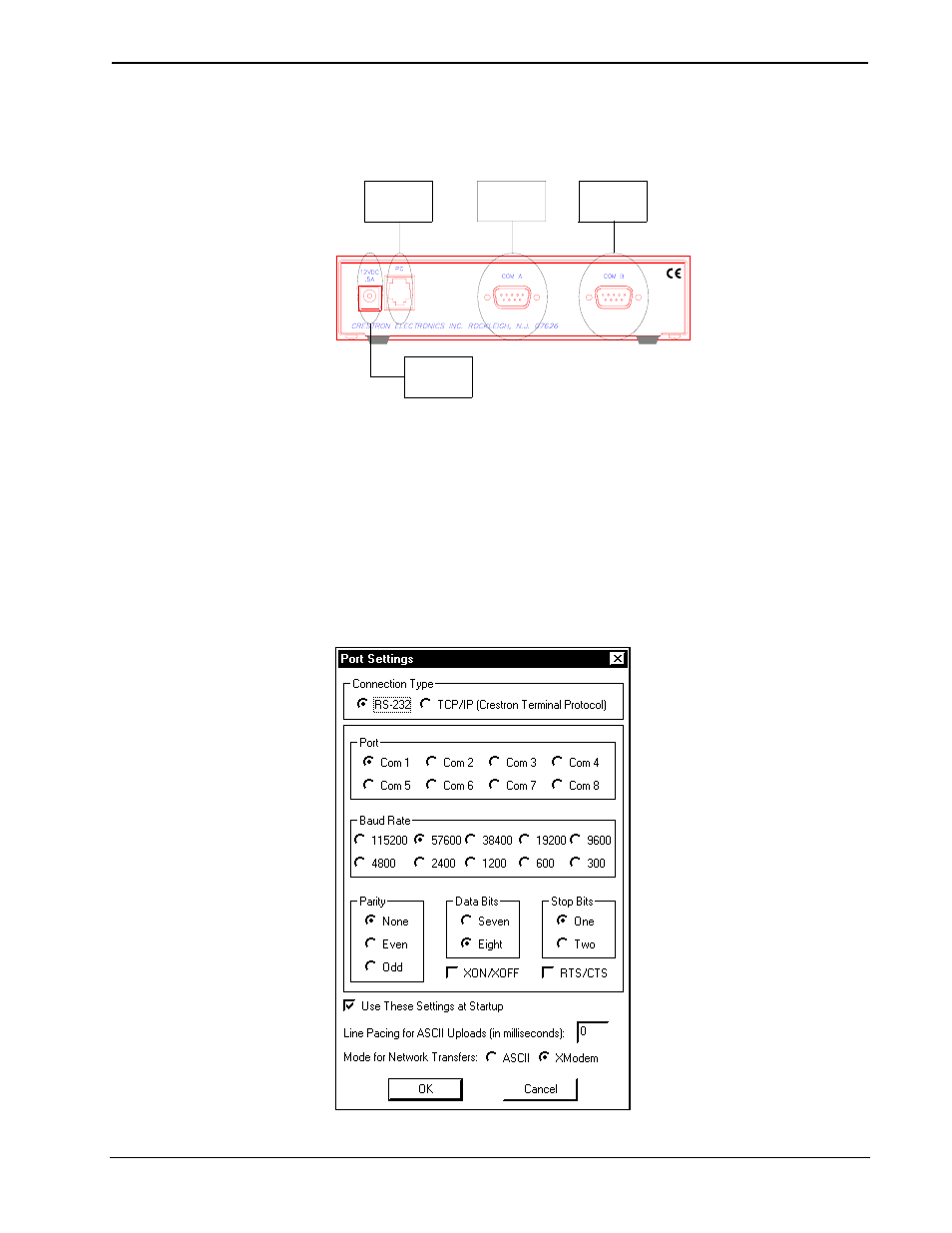
Hookup Connections for CEN-COM
SERIAL
DEVICE
SERIAL
DEVICE
PC
(USED ONLY
WHEN ACCESSING
SETUP MENUS)
POWER PACK
(500 mA)
(1000 mA
for CENI-COM)
NOTE:
CABLES ARE NOT SUPPLIED.
ETHERNET CONNECTION NOT SHOWN.
Setup Menus
The CEN-COM setup menus can be accessed only after connecting the
communications port of the PC to the PC port on the CEN-COM. Communication
cables are not provided. Refer to “Hardware Hookup” in the previous section for
CEN-COM hookup details. After connecting the CEN-COM and before applying
power to it, open the communications package that resides on the PC. Viewport from
either SIMPL Windows or VisionTools Pro is used in the illustrations that follow. Be
sure to set the PC communication parameters as shown after this paragraph. No
handshaking is required.
PC Communication Parameters
Operations Guide - DOC. 5719
Ethernet RS-232/422 COM Module: CEN-COM
• 7