Chateau™ decorative gas appliance, Framing and finishing – Vermont Casting DVT38S2 User Manual
Page 6
6
Chateau™ Decorative Gas Appliance
20009543
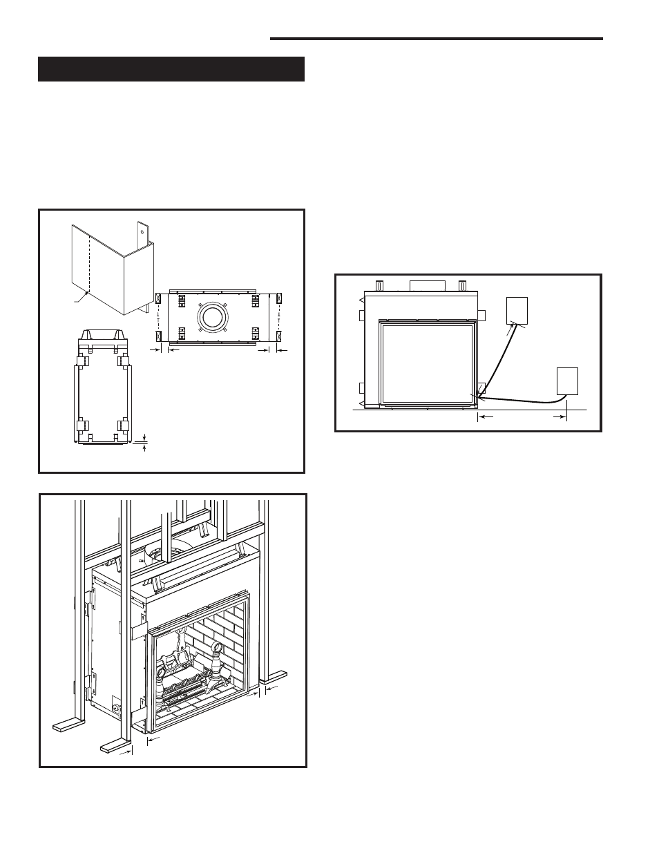
Framing and Finishing
NOTE: The valve box assembly must be installed in
the same room as the fireplace.
1. Choose the unit location.
2. The unit is shipped with four (4) nailing flanges
mounted near the front corners on the side with the
valve box assembly . (Fig. 4)
3. Frame the fireplace with a header across the top of
the standoff. (Fig. 5) It is very important to allow for
the finished wall face along with marble, tiles or any
other noncombustible face finish material desired
when setting the depth of the framing.
4. Attach the fireplace nailing flanges to the frame as
shown in Figure 4.
5. The gas components are located in the control
panel assembly attached to the right side of the unit.
Choose the desired location on the wall or mantel
for the valve box assembly. The conduit length is 5’
(1524 mm). (Fig. 6) The framing dimensions for the
box are 12¹⁄₄”L x 9¹⁄₄”W x 5⁵⁄₈”D (311 x 235 x 143 mm).
When the framing for the box is complete, remove
the screws securing the valve box to the outer cas-
ing. Carefully remove the valve box and, without
stressing the conduit, slide the box into the framed
opening. Replace the screws removed from the side
of the outer casing.
6. To secure the valve box assembly to the framing
members, open the box door, remove extension
knob(s), remove the valve cover by removing the
two (2) screws securing the valve cover to the box,
hold the cover plate with one hand and disconnect
the wires to the switch and pilot indicator (R models
only). NOTE: Do not allow the valve cover plate to
hang from the pilot indicator wires as this could dam-
age the wires. Secure the box to the framing through
the two (2) holes at the top and one (1) on each
side using sheet rock screws. (Fig. 7) After fram-
ing the box, replace the wires, the valve cover, the
extension knob(s) in reverse order. NOTE: The pilot
indicator body is labelled +/-, make sure the positive
wire on the pilot indicator goes to ground and the
negative goes to the plug between the valve and the
thermocouple.
7. The U-channel located on the top of the unit as well
as the nailing flanges on the sides that were men-
tioned in Step 1, are designed to accommodate non-
combustible board (recommended Dura-Rock). They
are positioned 1” (25mm) back from the face of the
unit. NOTE: The U-channel depth can be adjusted
by loosening the hex nut inside the channel.
FP1357b
DVT38s2nailing flanges
3/17/04 djt
6"
(152 mm) Min.
1"
(25 mm) Min.
1���"
(38mm)
Max. Hearth Height
FP1357a
Fig. 4 Nailing flanges.
Bend
Line
FP1467a
DVT38s2
framing
6/05 djt
1"
(25 mm)
6"
(152 mm)
Fig. 5 Fireplace framing.
FP1467a
FP1361
Fig. 6 Valve box assembly location.
������������
������������
������
���������������
��������
�������������