Chateau™ decorative gas appliance, Sidewall applications – Vermont Casting DVT38S2 User Manual
Page 13
13
Chateau™ Decorative Gas Appliance
20009543
Since it is very important that the vent-
ing system maintain its balance between
the combustion air intake and the flue
gas exhaust, certain limitations as to vent
configurations apply and must be strictly
adhered to.
The vent graph showing the relationship between verti-
cal and horizontal side wall venting will help to deter-
mine the various dimensions allowable.
Minimum clearance between vent pipes
and combustible materials is 3¹⁄₂” (89 mm)
on top, 2¹⁄₂” (64 mm) on both sides and 1¹⁄₂”
(38 mm) on the bottom.
When the vent termination exits through foundations
less than 20” (508mm) below siding outcrop, the vent
pipe must be flush with the siding.
Sidewall Applications
FP1453
DVT38s2
Top vent max run
3/17/04 djt
NOTE: Apply high temperature sealant or UL approved
high temperature metal adhesive tape as directed on Page
11.
14’
(4.3m)
Pipe Straps
Every 3’
(914mm) Firestop/Zero
Clearance Sleeve
Pipe
Straps
Every 3’
(914mm)
20’ (6m)
FP1453
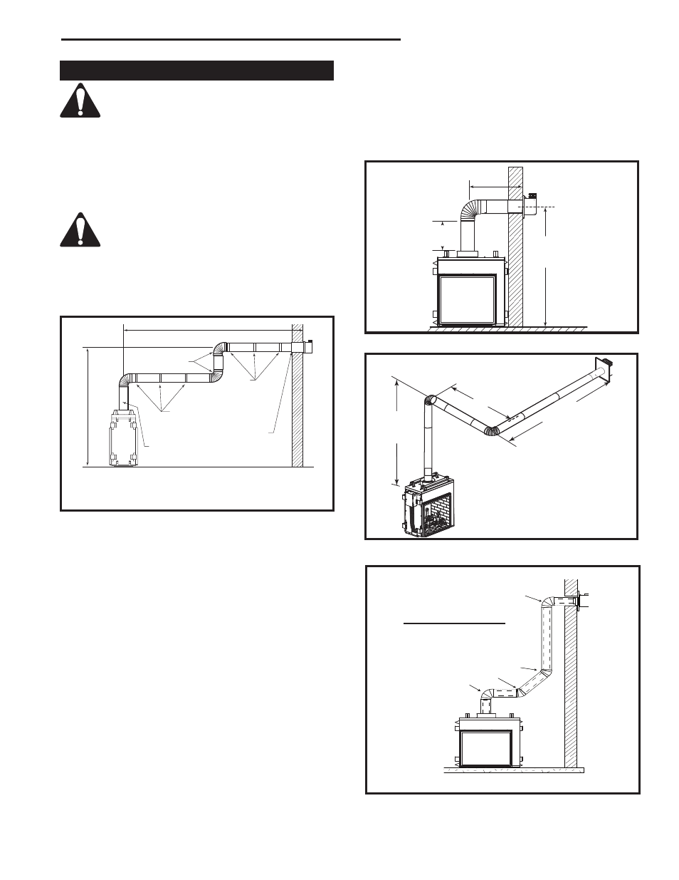
Fig. 15 Support straps for horizontal runs.
Minimum 2’
(610mm) Section
Unitized Elbow
(SK890)
It is always best to locate the fireplace in such a way
that minimizes the number of offsets and horizontal
vent length of vent pipe from the flue collar of the fire-
place to the face of the outer wall.
Horizontal plane means no vertical rise exists on this
portion of the vent assembly.
•
The maximum number of 90° elbows per side wall
installation is three (3), but must not have two (2)
consecutive elbows in the horizontal plane.
•
A minimum of 2’ (610mm) vertical section off the top
of the unit is required, an elbow and a 1’ (305mm)
maximum horizontal run to get through a wall. (Fig.
16)
•
The maximum number of 45° elbows permitted per
side wall installation is two (2). These elbows can be
installed in either the vertical or horizontal run. (Fig.
16)
•
For each 45° elbow installed in the horizontal run,
the length of the horizontal run MUST be reduced by
18” (45 cm). This does not apply if the 45° elbows
are installed on the vertical part of the vent system.
For each 90° elbow installed in the horizontal run,
the length of the horizontal run MUST be reduced by
36” (914 mm).
•
The maximum number of elbow degrees in a system
is 270°. (Fig. 18)
3'
(914mm)
FP1454
DVT38s2
horizontal plane
3/17/04 djt
2'
(610mm)
6'9���"
(2080mm)
CL
FP1454
Fig. 16 Minimum vertical run / maximum horizontal run.
Wall Opening
10'
(3m)
A
A + B = 17' (5.2m)
B
FP1238
Fig. 17 Maximum vent run with elbows.
Example:
Elbow 1
= 90°
Elbow 2
= 45°
Elbow 3
= 45°
Elbow 4
= 90°
Total angular variation = 270°
FP1455
Fig. 18 Maximum number of elbow degrees.
1
2
4
• • • • • • • • • • • •
• •• • • • •••• • • •• • • • • • • • • • • • • • • • • • •
• • • • • • • • • •
• • • • • • • • • • • • • •
• •• • •• • ••• ••••••••••••••
3