Processor module, Removing the processor module, Replacing the processor module – Dell Latitude 120L User Manual
Page 11
Back to Contents Page
Processor Module
Dell™ Latitude™ 120L Service Manual
Replacing the Processor Module
Removing the Processor Module
1.
Follow the instructions in
Before Working Inside Your Computer
.
2.
Turn the computer upside-down.
3.
Remove the processor thermal-cooling assembly. See
4.
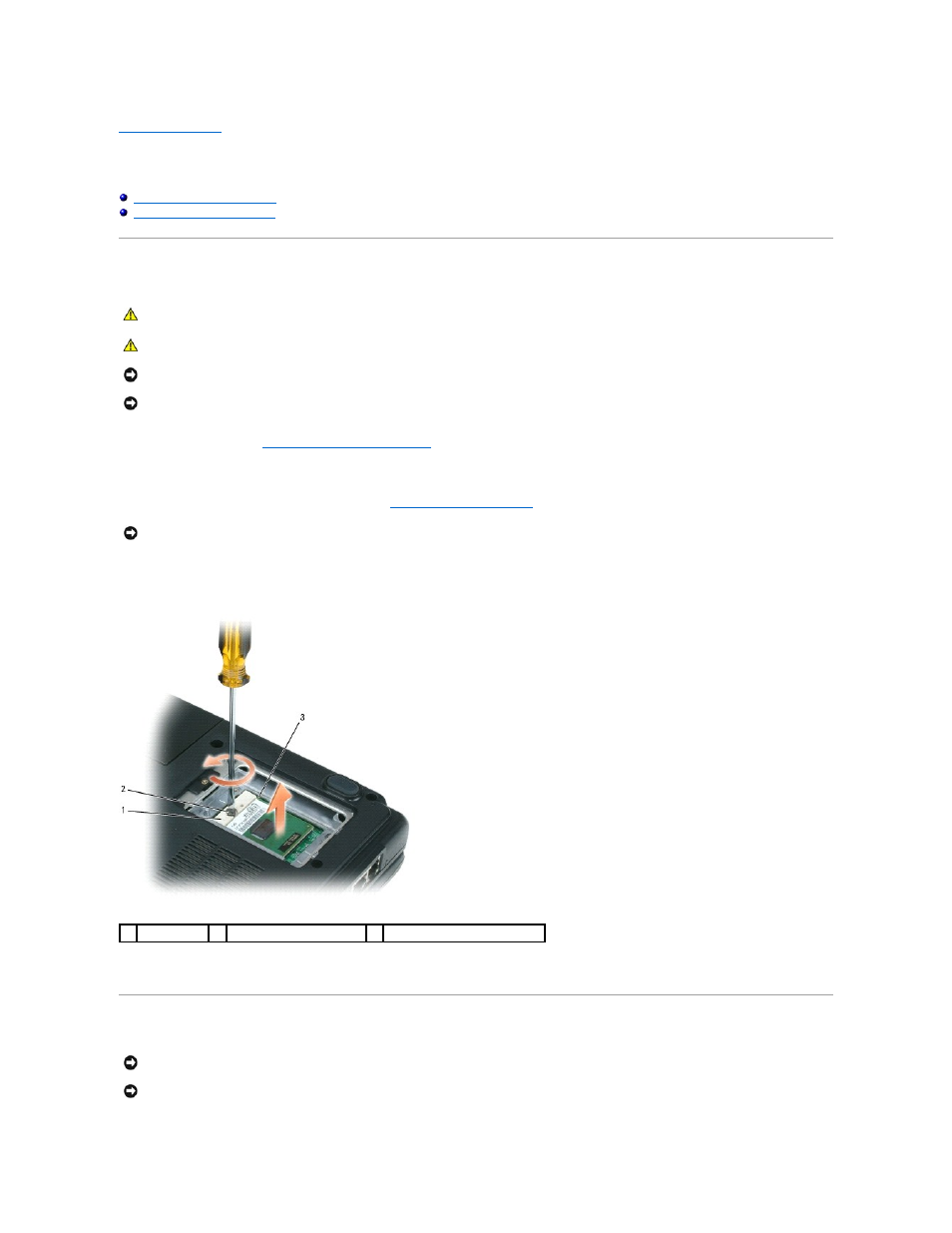
To loosen the ZIF socket, use a small, flat-blade screwdriver and rotate the ZIF-socket cam screw counterclockwise until it comes to the cam stop.
The ZIF-socket cam screw secures the processor to the system board. Take note of the arrow on the ZIF-socket cam screw.
5.
Use a processor extraction tool to remove the processor module.
Replacing the Processor Module
CAUTION:
Before performing the following procedures, follow the safety instructions in the Product Information Guide.
CAUTION:
To prevent static damage to components inside your computer, discharge static electricity from your body before you touch any of
your computer's electronic components. You can do so by touching an unpainted metal surface.
NOTICE:
Press and hold the processor down by applying slight pressure to the center of the processor while turning the cam screw to prevent
intermittent contact between the cam screw and processor.
NOTICE:
To avoid damage to the processor, hold the screwdriver so that it is perpendicular to the processor when turning the cam screw.
NOTICE:
When removing the processor module, pull the module straight up. Be careful not to bend the pins on the processor module.
1
ZIF socket
2
ZIF-socket cam screw
3
pin-1 corner of processor
NOTICE:
Ensure that the cam lock is in the fully open position before seating the processor module. Seating the processor module properly in the ZIF
socket does not require force.
NOTICE:
A processor module that is not properly seated can result in an intermittent connection or permanent damage to the processor and ZIF
socket.