Maintenance instructions, Removing cam-checks, Warning – Ames Fire & Waterworks 6000HMB Portable Hydrant Meter Backflow Preventers with Meter Housing User Manual
Page 3
3
WARNING
!
Depressurize valve before servicing.
Removing Cam-Checks
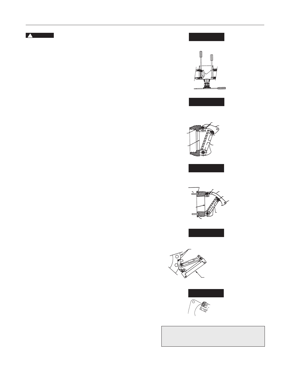
1. Shut down water system and lock out system if possible. Slowly
open all ball valves to relieve air and water pressure. Loosen
bolts on groove coupler and remove groove coupler and cover
plate from valve body.
2. Remove #1 Cam-Check Assembly by using your hands to
unscrew (turn counterclockwise) Cam-Check and remove
through top access port. Do not use Cam Arm as a handle
to unscrew Cam-Check. If Cam-Check cannot be loosened
by hand, insert a long screwdriver between valve body and
Cam-Check (see Figure 3). Gently apply pressure against the
Cam-Check until loosened. Finish unscrewing by hand. Un-
screw #2 Cam-Check (turn counterclockwise) by placing a long
screwdriver across lugs and applying pressure to loosen #2
Cam-Check. Finish unscrewing by hand.
3. To clean #1 Cam-Check (except 2
1
/
2
" – 4" (65-100mm) DC
Check), locate the Cam Arm opening stud on the outlet flange
of the valve assembly. Slide the Cam Arm over the stud with the
check threads facing downward (Figure 5A). Tighten
1
/
4
" nut on
stud to secure cam bar. Slowly pull the assembly outward to
open check. The clapper so that the end of the Cam Arm rests
between roller and clapper (Figure 5B).
Thoroughly clean the seat area and clapper sealing surfaces of
both Cam-Checks. Rinse Cam-Checks and O-rings thoroughly.
Inspect seats, clapper sealing surfaces, Cam Arms, and O-rings
for damage, nicks, and debris. If damaged, install a new Cam-
Check assembly and/or O-ring or shutoff disc.
4. Before reinstallation of check assembly, thoroughly clean
O-ring groove and lubricate with F.D.A. approved lubricant.
Insert and thread #2 Cam-Check first and then #1 Cam-Check.
#2 Cam-Check should be tightened by inserting a long screw-
driver between lugs to tighten firmly (see Figure 2). Do not over
tighten. Tighten #1 Cam-Check firmly by hand only. Replace
cover plate, clean groove coupler gasket and groove. Replace
groove coupler. Close ball valves. Repressurize and bleed air
from all test cocks.
Maintenance Instructions
Figure 2
#1 Cam
Check
#2 Cam
Check
Screwdriver
A
B
C
#1 Cam Check
2
1
/
2
" – 6" (65-150mm) RP (Short Cam)
Figure 3
O-ring Seal
& Groove
Seat
Clapper
Roller
Spring
Cam Arm
Figure 4
#2 Cam Check DC & RP
O-ring Seal
& Groove Lug
Seat
O-ring Seal & Groove
Clapper
6" Only
Roller
Cam Arm
Spring
Figure 5A
Cam Bar Open Pin
Valve Outlet Flange
Threaded Stud on Flange
6" (150mm) 1st Check DC
6" (150mm) 2nd Check
DC & RP
Figure 5B
Cleaning
Position
For repair kits and parts, refer to our Backflow Pre-
vention Products Repair Kits & Service Parts price list
PL-A-RP-BPD found on
www.amesfirewater.com.