Testing — double check valve assemblies, Test check valve no. 1, Test check valve no. 2 – Ames Fire & Waterworks ATG-1 Backflow Preventer Test Kit User Manual
Page 4: Test for leaky no. 2 shutoff
Test Check Valve No. 1
Step 1: Ensure shutoff #1 is open, shutoff #2 is closed.
Step 2: Connect high side hose to test cock #3, low side to test cock #2
and open both test cock #2 and test cock #3.
Step 3: Open valve C, then open A to bleed air from the high side. Close
valve A, then open B to bleed low side. Close valve B.
Step 4: Connect vent hose loosely to test cock #1. Open valve A to vent
air from vent hose. Tighten vent hose at test cock #1, open test
cock #1.
Step 5: Close shutoff #1. Slowly loosen hose at test cock #2 until dif-
ferential gauge rises to 2psi and retighten hose. If the differential
reading does not decrease, record check valves as “tight”.
Test Check Valve No. 2
Step 1: Move the high side hose to test cock #4, low side to test cock
#3 and open both test cock #3 and test cock #4. Remove vent
hose from test cock #1, open shutoff #1.
Step 2: Open valve C, then open valve A to bleed air from the high
side. Close valve A, then open valve B to bleed low side. Close
valve B.
Step 3: Connect vent hose loosely to test cock #1. Open valve A to
vent air from the vent hose. Tighten vent hose at test cock #1,
open test cock #1.
Step 4: Close shutoff #1, then slowly loosen hose at test cock #3
until differential gauge rises to 2psi and retighten hose. If the
differential reading does not decrease, record check as tight.
Remove all hoses and restore valve to original working condition.
Note: The assembly will fail both the first and second check valve
tests above, if shutoff #2 leaks excessively. To test for a leaky #2
shutoff, use the following procedure.
Test for Leaky No. 2 Shutoff
Step 1: Connect the high side to test cock #1, low side to test cock #4.
Open test cock #1 and test cock #4. Close shutoffs #1 and #2.
Step 2: Close valve C. Open valve A, then open valve B
1
⁄
2
turn, loosen
hose at test cock #4 to remove air. Retighten hose.
Step 3: If the differential gauge rises above 0, there is excessive
leakage at shutoff #2 and it must be replaced to test the
assembly.
Note: Product information is subject to change without notice and
supersedes all previous publications.
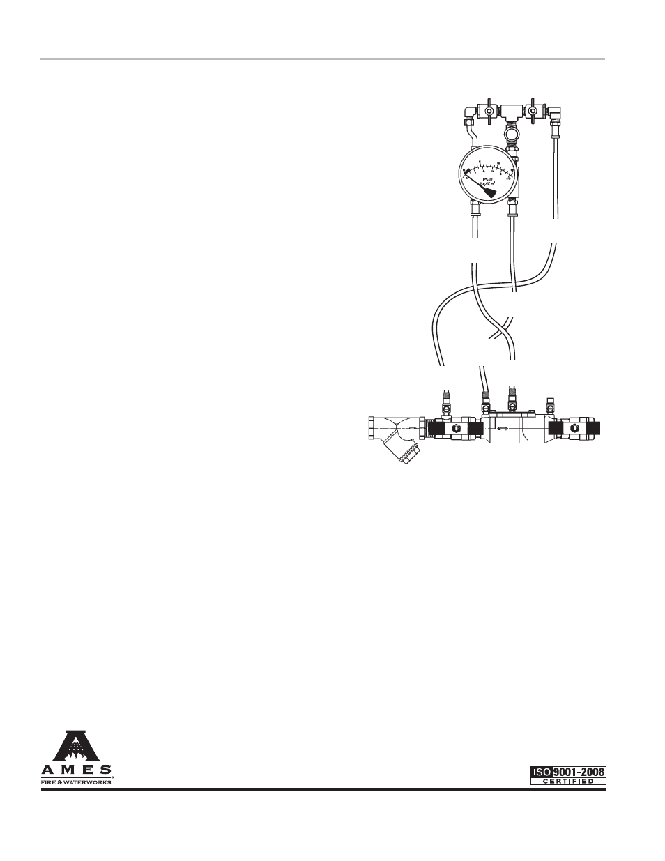
Testing — Double Check Valve Assemblies
Ball Type Test Valves
(A)
(C)
(B)
Needle
Valve
High Hose
(Yellow)
Low Hose
(White or Red)
Vent Hose
(Blue)
Test Cock
No. 1
Test Cock
No. 2
2000B shown
Test Cock
No. 3
Test Cock
No. 4
IS-A-ATG-1 0904
EDP# 1915327
© 2011 Ames Fire & Waterworks
www.amesfirewater.com
A Watts Water Technologies Company
USA: Backflow- Sacramento, CA • Tel: (916) 928-0123 • Fax: (916) 928-9333
Control Valves- Houston, TX • Tel: (713) 943-0688 • Fax: (713) 944-9445
Canada: Burlington, ON • Tel: (905) 332-4090 • Fax: (905) 332-7068