Installation, Materials, Installation practices – Ames Fire & Waterworks IBR In-Building Risers User Manual
Page 3: Field test procedures, Constrained piping, Free piping
3
Installation
Materials
Because the In-Building Riser is buried, the material of
construction has been chosen as Type 304L Stainless Steel.
This material is generally recognized as a corrosion resistant
material which is superior to Cast, Ductile Iron, or Coated
Steel pipe for corrosion resistance, and which is superior to
engineered plastics for strength and longevity. In general,
the stainless steel is the cathode in joints of dissimilar metal,
so that any corrosion which may occur will not affect the
stainless steel. In addition, an extra protection is provided
in that there is no actual metal to metal contact at either
joint due to the CIPS bell connection design and the groove
coupler design.
Installation Practices
Good installation practice for all types of buried pipe often
calls for wrapping of the pipe to decrease corrosion due to
soil conductivity. Although stainless steel is less susceptible
to corrosion, local codes and general practices should still
be followed.
Field Test Procedures
Normal field test procedures call for a hydrostatic pressure
test of the system prior to final acceptance. Often, segments
of the system will be tested individually prior to the complete
system test. In order to hydrostatically test the In-Building
Riser as installed, two methods are recommended.
1. Constrained Piping
If the piping installation is essentially complete, the piping
restraints may adequately take the thrust loads generated by
having a blind end on the pipe system. In these cases, no
special actions to restrain thrust or side loads are required,
and the fitting installed in the system may be adequate for
hydrostatic testing.
2. Free Piping
If just the riser or riser/main connection is to be tested, then
the thrust loads from the blind end cap on the riser may need
to be restrained. The riser design has been tested in the
unrestrained state using a rigid coupler and end cap grooved
fitting. Flange adapters, expansion fittings, or other styles
of end connectors may result in excessive end thrust which
may cause a leak or fitting malfunction. In addition, couplings
which are adequately rated for high pressure testing should
be used if thrust restraints are not feasible.
Note: It is important that all air is bled from the system before pressurizing
any component.
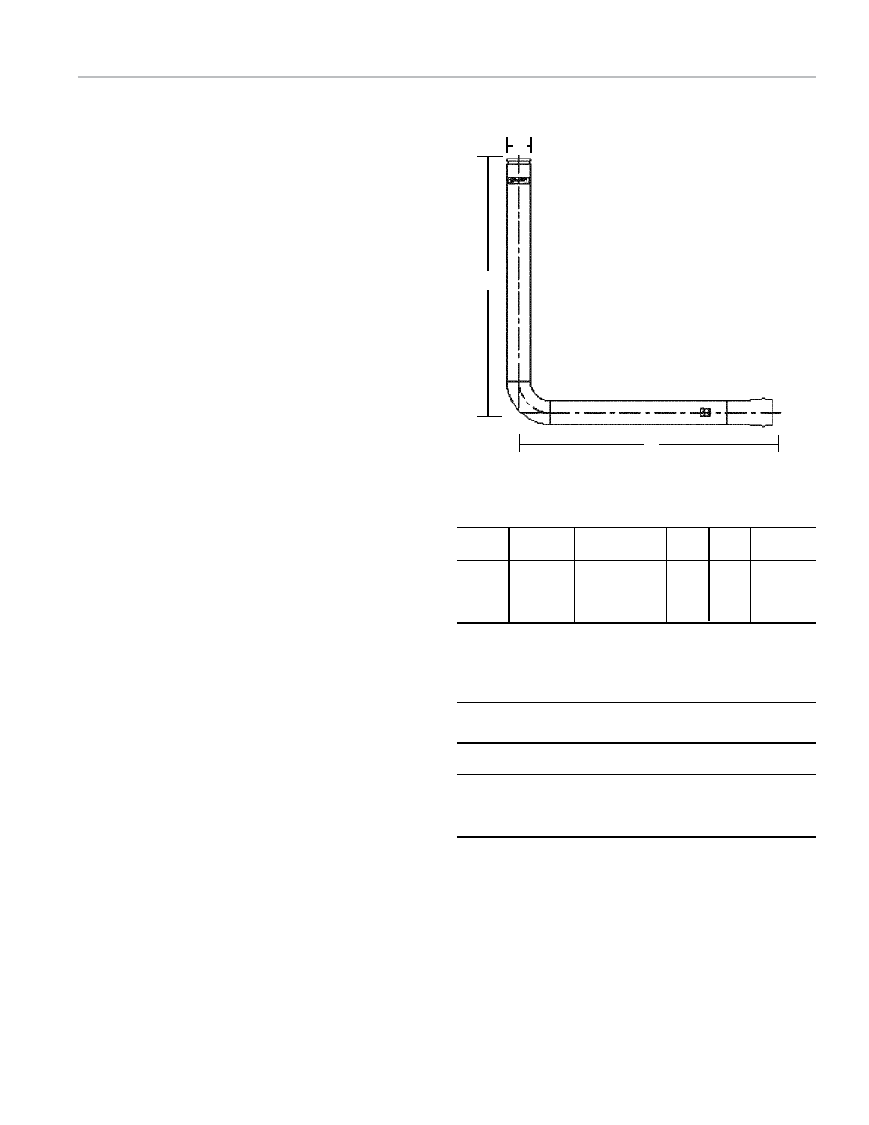
A
B
C
Dimensions/Weights
Size Ordering
A
B C Weight
in. mm
Code
inch ft.
ft.
lbs.
4 100
0690970
4
1
⁄
2
OD
6
6
71
6 150
0690969
6
5
⁄
8
OD
6
6
98
8 200
0690968
8
5
⁄
8
OD
6
6
129
10 250
0690971
10
3
⁄
4
OD
6
6
202
End Connections
Bell End: Mates with Ductile Iron Pipe and AWWA C900 Pipe (PVC Pipe with Cast Iron
Pipe Equivalent OD's)
Size
Sealing Gasket (CIPS – C900)
in. mm
Mating Pipe OD
Spare Part Ordering code
4 100
4.80
7014421
6 150
6.90
7014422
8 200
9.05
7014423
10 250
11.10
7014424
Utilizes Gasket conforming to UL 157 with “Lock in” gasket configuration.