Basic installation instructions – Ames Fire & Waterworks IBR In-Building Risers User Manual
Page 2
Ames Company In-Building Risers are designed for easy
installation in standard configurations as outlined using
standard construction method.
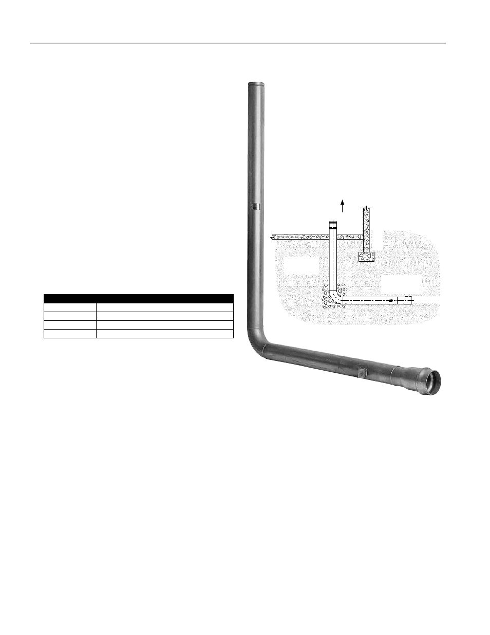
The floor penetration detail of the In-Building Riser shall be
restrained per direction outlined by site plans. Consult Uni-
Bell handbook of PVC pipe if instructions are not provided.
The below ground connection is a standard AWWA C900
gasketed coupler (either ductile iron or PVC). Installation in
accordance with the following information (from Uni-Bell
handbook).
1. Clean out inside of coupler making certain the beveled
spigot end and the gasket groove are free of dirt.
2. Apply lubricant to beveled spigot (male).
3. Insert gasket into coupling groove and seat firmly.
4. Push lubricated end past gasket into the bell housing. (Ames
in-building risers are equipped with the lugs placed 180°
apart on either side of the unit which can be used to “pull”
the pipe into the bell using a “come a-long” type equipment.
Also, the “bar and block method described in the Uni-Bell
handbook can also be used for installation).
5. The maximum allowable pipe deflection angle between the
IBR and underground pipe is as follows:
The above ground connection is an AWWA specification C606
groove. All underwriters Laboratory approved groove couplers
made to fit the AWWA C606 grooves can be used to join the
connection to the in-building supply line.
1. Check gasket and lubricate it using groove coupler manu-
facturer's recommended lubricant or approved equal.
2. Install gasket. Place gasket over pipe end being sure gasket
lip does not overhang pipe end.
3. Align and bring two pipe ends together and slide gasket into
position centered between grooves or each pipe (no portion
of the gasket should extend into the groove of either pipe.)
4. Apply housings. Place housings over gasket, being sure
the housing keys engage into the grooves of the pipe. (No
portion of the gasket should extend into the groove of either
pipe.)
5. If restraint fitting is being used tighten nuts: Tighten nuts
alternately and equally until housing bolt pads are firmly
together metal to metal: Uneven tightening will cause gasket
to pinch.
Important: Inquire with governing authorities for local
installation requirements.
attn. Installer: after Installation, please leave this instruction
sheet for occupant's information.
2
Basic Installation Instructions
Grooved End
Flow
Building Perimeter
Building
Floor
CIPS Cou-
plings
Flow
TR Size
Maximum Deflection
4"
1°
6"
1°
8"
1°
10"
1°