Installation, Mounting, Factory settings – Baumer BA IRxx.DxxL User Manual
Page 5: Sensor alignment, Installation accessories, 3installation, 1 mounting, 2 factory settings, 3 sensor alignment, 4 installation accessories
en_BA_IRxx
.DxxL.docx
5/12
Baumer Electric AG
10.11.2014 14:03/simg V1.0 ANW_81146130
Frauenfeld, Switzerland
3
Installation
3.1 Mounting
The sensors have a threaded housing and can be fixed with the nuts which are part of the delivery. The
maximal mounting torque is depending on the housing material and the thread size:
Stainless steel thread
o M8 = 10 Nm
o M12 = 20 Nm
o M18 = 55 Nm
Brass nickel plated thread
o M8 = 7 Nm
o M12 = 15 Nm
o M18 = 40 Nm
Reduce torque values by 30 % at the sensor’s face. The position and the material of the nuts can have an
influence on the analog output curve, see chapter 4.4.
3.2 Factory Settings
In the mounting instructions it is described how the sensors behave once they leave the factory or if the
factory reset teach procedure is activated.
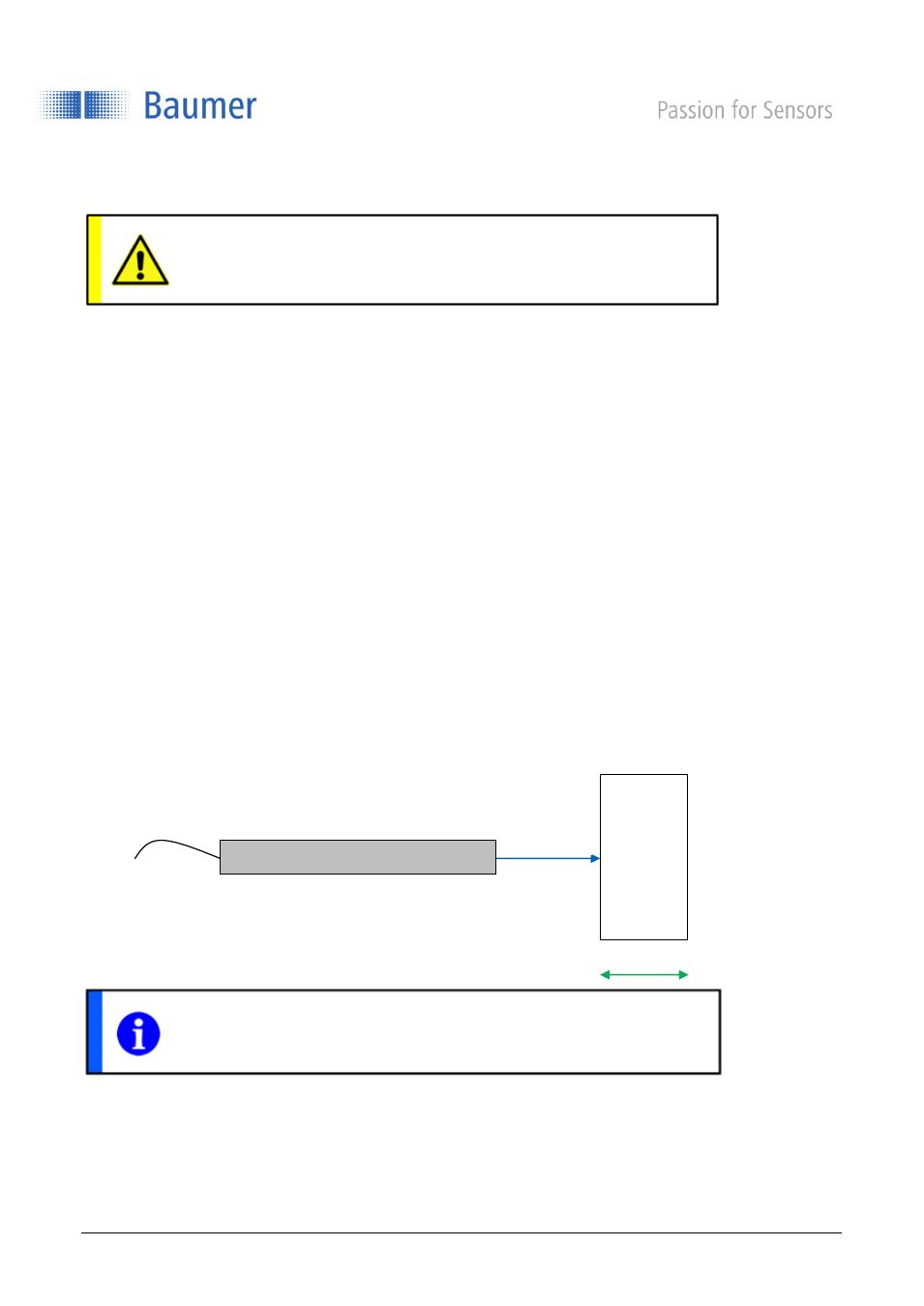
3.3 Sensor alignment
As standard the sensor is mounted at a right angle (90°) to the object (standard installation).
Other sensor alignments are possible; please contact Baumer for further guidance.
3.4 Installation accessories
To ensure optimal mounting, various mounting brackets are available an as accessory, see www.baumer.com.
ATTENTION!
Connection, installation and commissioning may only be performed by qualified
personnel.
NOTE
Angle deviations can affect measuring accuracy.
Me
ta
lli
c
ob
je
c
t
Distance s
Direction of movement
Sensor