0ab47, 3the rs-232 interface, 2 structure of commands – Baumer BA Series09 US RS232 User Manual
Page 4
Bedienungsanleitung_Series09-US_RS232_V1_e.doc
4/11
Baumer Electric AG
26.03.2013 14:43:00/tof
Frauenfeld, Switzerland
3
The RS-232 interface
3.1
General notes
•
Step 1: Setting of the sensitivity mode A-D; Step 2: Teaching of the Scanning range
•
In measuring mode: Yellow LED flashing = weak signal received. Conceivable corrective measures: teach
object anew; move object closer to sensor; clean transducer.
•
In measuring mode: Red LED on = object within blind range
•
Provided the Teach-in sequence cannot be successfully completed the sensor defaults automatically to the
previously saved settings.
•
Power must be switched off before connecting the sensors.
•
A soiled beam columnator may generate erroneous output signals. Therefore it must be checked from time
to time and cleaned if necessary.
•
Via the RS 232 interface measured data can be received and a number of functions are configurable.
•
The sensors work with a baud rate of 115’200
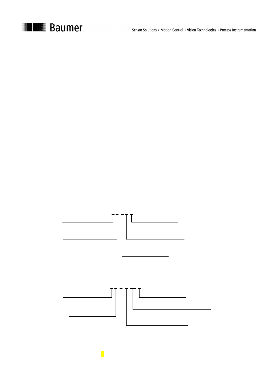
3.2 Structure of commands
All commands consist of ASCII characters only. One character consists of 1 start-Bit, 8 data-Bits and 1 Stop-
Bit.
Address
Address „0“ is the broadcast address, which is accepted by every sensor and which must be used when
using RS232.
Telegram sent by the control to the sensor:
{0AB}
NO CHECKSUM!
Telegram (sensor response) sent from the sensor to the control:
{0AB47}
For examples refer to chapter "3.8 Examples".
Address 1 number 0...8,
for RS232 always 0
Command
Character (A..Z)
Start of Frame (SOF)
X characters
(depends on the command)
End of Frame (EOF)
Address 1 number
0...8, for RS232
always 0
Command
Character (A..Z)
Start of Frame (SOF)
X characters
(depends on command)
End of Frame (EOF)
Checksum 2 Byte, see appendix