Principle of operation, 1 general – Dynalco SWTD-1000 Speed Switch/Transmitter User Manual
Page 9
Operating Instructions SWTD-1000
DYNALCO
7
//
4.
Principle of Operation
4.1 General
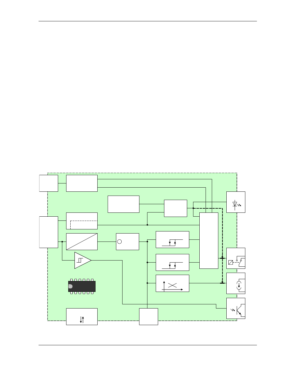
The SWTD-1000 is controlled by a microprocessor. It works according to the period measurement
principle whereby the input period is measured with subsequent computing of the reciprocal value
corresponding to the frequency or speed. The relationship between frequency and speed is established
with the Machine factor.
The current output and relay control are determined from the speed.
The relay function is defined via 2 selectable parameter sets. Each parameter set can access the 2 limit
values, the alarm definition, sensor monitoring and other process values.
The 2 limits each have and upper and lower set point (hysteresis setting)
The selection of the valid parameter set is via the binary input.
The relay status may be held until reset via the binary input
The system continuously monitors itself. In addition the sensor may be monitored. Dependent upon the
configuration, these conditions can influence the relay and current output.
The alarm status is indicated via the front panel LED.
The frequency output (open collector output) is not influenced by the machine factor and corresponds to
the input signal frequency.
The input of all parameters is via PC software and the RS232 interface. This may also be used to
interrogate the unit’s settings, measurement and general status.
Parameters are retained in an EEPROM.
Sensor supply
Sensor control
Periodic time
measurement
Frequency
calculation
Machine
factor
X
Definition limit 1
Definition limit 2
Definition current output
Definition
Relay
Analysis of the
binary input
Reset
Choice of the parameter set A/B
Sensor failure
Frequency
Speed
System failure
System control
Definition Alarm
LED
Relay
Current
output
Open
Collector
Sensor
connection
binary
input
RS 232
EEPROM
Display