4 fault behavior, 5 power supply interruption, 5 binary input – Dynalco SWTD-1000 Speed Switch/Transmitter User Manual
Page 21: 1 sensor fault (sensor monitoring), 2 system alarm, 3 alarm
Operating Instructions SWTD-1000
DYNALCO
19
//
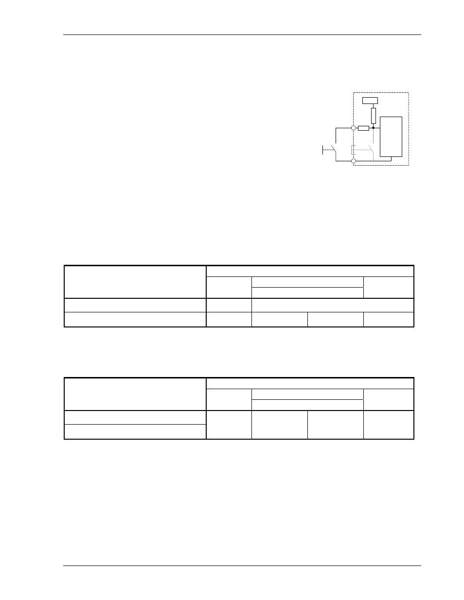
9.3.5 Binary Input
2 functions are executable using the binary input:
• Switching between parameter sets A and B. See 0 9.3.2 Parameter set A and B.
• Resetting a latched relay. See 9.3.3 Relay.
The binary input has an internal pull up resistor to +5V and is
therefore normally logic High.
Shorting the binary input to the sensor supply 0V creates a logic
0.
Switching the input for between 0.1 and 0.3 seonds resets a
latched relay but does not influence parameter set selection,
which requires longer than 0.3 seconds.
9.4 Fault Behavior
9.4.1 Sensor Fault (Sensor Monitoring)
The sensor may be monitored in 2 ways. With sensors powered by the SWTD-1000 the sensor
supply current is monitored. If the current falls outside the permitted range then sensor fault is
indicated. If the sensor is not powered by the SWTD-1000 then it may only be monitored for
disconnection. If disconnected, sensor fauly is indicated.
The SWTD-1000 behavior in the event of a sensor fault is dependent on the configuration:
Outputs in the event of a sensor fault
Analog output
Alarm Configuration
LED
Current
Relay
Only System error
On
Measured value output per configuration
System error OR Sensor monitoring
Off 0mA 0V
deactivated
9.4.2 System Alarm
If the microprocessor detects a checksum fault (RAM, ROM or EEPROM) the measured value is set to
0rpm, the analog output goes to 0/4mA and the relay is deactivated.
Outputs in the event of a System alarm
Analog output
Alarm Configuration
LED
Current
Relay
Only System error
System error OR Sensor monitoring
Off 0mA 0V
deactivated
9.4.3 Alarm
As long as a combined alarm is present no measurements are conducted and the outputs behave as
described above. Once the fault or alarm condition is removed the last correct measured value is
assumed. Eventual limit activation is not taken into account.
9.5 Power Supply Interruption
If the PSU remains off for longer than the permitted period the outputs deactivate i.e. the analog output
goes to 0mA, the relay deactivates and the “open collector“ ouput becomes high resistance.
Once the supply resumes in range the SWTD-1000 begins its initialization routine.
5 Volt
parameter set A B
analysis
+Bin
OVS
pushbutton
10k