Cooper Instruments & Systems Series M4 Digital Force Gage User Manual
Page 10
CF 182
7
32-1117 1010
or alarm indication in process control applications. Two limits, high and low, are specified and stored in the
non-volatile memory of the instrument and the primary reading is compared to these limits. The results of the
comparisons are indicated through the three outputs provided on the 15-pin connector, thus providing
“under”, “in range”, and “over” signaling. These outputs can be connected to indicators, buzzers, or relays as
required for the application.
7.2 Configuration
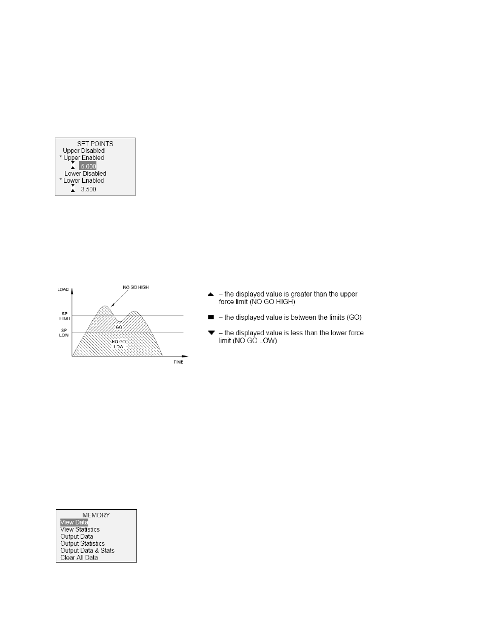
To configure set points, select Set Points from the menu. The screen will appear as follows:
Either one, two, or none of the set points may be enabled. To toggle between the tension and compression
directions, press the DIRECTION key.
If two set points have been enabled, they are displayed in the upper left corner of the display. If only one set
point has been enabled, the word “OFF” will appear in place of the value. If no set points have been enabled,
the upper left corner of the display will be blank.
9
When set points are enabled, the following indicators are shown to the left of the primary reading:
Note: Set point indicators and outputs reference the displayed reading, not necessarily the current live load.
8 DATA MEMORY AND STATISTICS
Series 4 gauges have storage capacity of 50 data points. Readings may be stored, viewed, and output to an
external device. Individual, or all, data points may be deleted. Statistics are calculated for the data presently
in memory.
To enable memory storage, select DATA Key from the menu, then scroll to Memory Storage and press
ENTER. Then exit the menu. In the home screen, the data record number 00 will appear below the primary
reading. Press DATA at any time to save the displayed reading. The record number will increment each time
DATA is pressed.
To view, edit, and output stored readings and statistics, select Memory from the menu. The screen appears
as follows: