Description of parts, User responsibility – Amico Dome Loaded Manifold NFPA User Manual
Page 9
www.amico.com
9
M i c r o p r o c e s s o r D i g i t a l M a n i f o l d
P a g e : 4
USER RESPONSIBILITY
The information contained in this Installation and Maintenance Manual, pertains only to the ALERT-2
microprocessor based digital manifold. This product will perform in conformity with the descriptions
contained in this manual when assembled, operated, maintained and serviced in accordance with the
installation instructions provided.
The manifold
must be checked periodically. Parts that are broken, missing, worn, distorted or
contaminated,
must be replaced immediately. Should such repair or replacement become necessary,
please contact Amico Corporation or their distributors.
Installing CO2 and N2O manifolds outdoors. Please refer to NFPA Code: 5.1.3.3.1.8 Central
supply systems for nitrous oxide and carbon dioxide shall be prevented from reaching
temperatures lower than the recommendations of the central supply system’s manufacturer,
but shall never be lower than -7°C (20°F) or greater than 54°C (130°F).
All Manifolds should not be repaired or altered without prior written approval by Amico
Corporation or it’s distributors. Failure to comply will void all warranty on the manifold.
Statements in this manual preceded by the words
WARNING, CAUTION, DANGER and NOTE are of
special significance. Please read these sections carefully.
WARNING:
denotes steps which can prevent injury.
CAUTION:
denotes steps which can prevent damage to equipment.
DANGER:
denotes steps which can prevent electrical shock to equipment or to
prevent serious injury and/or death.
DANGER: Electrical shock hazard. Ensure that the main power source is turned
off during the connection of the power supply.
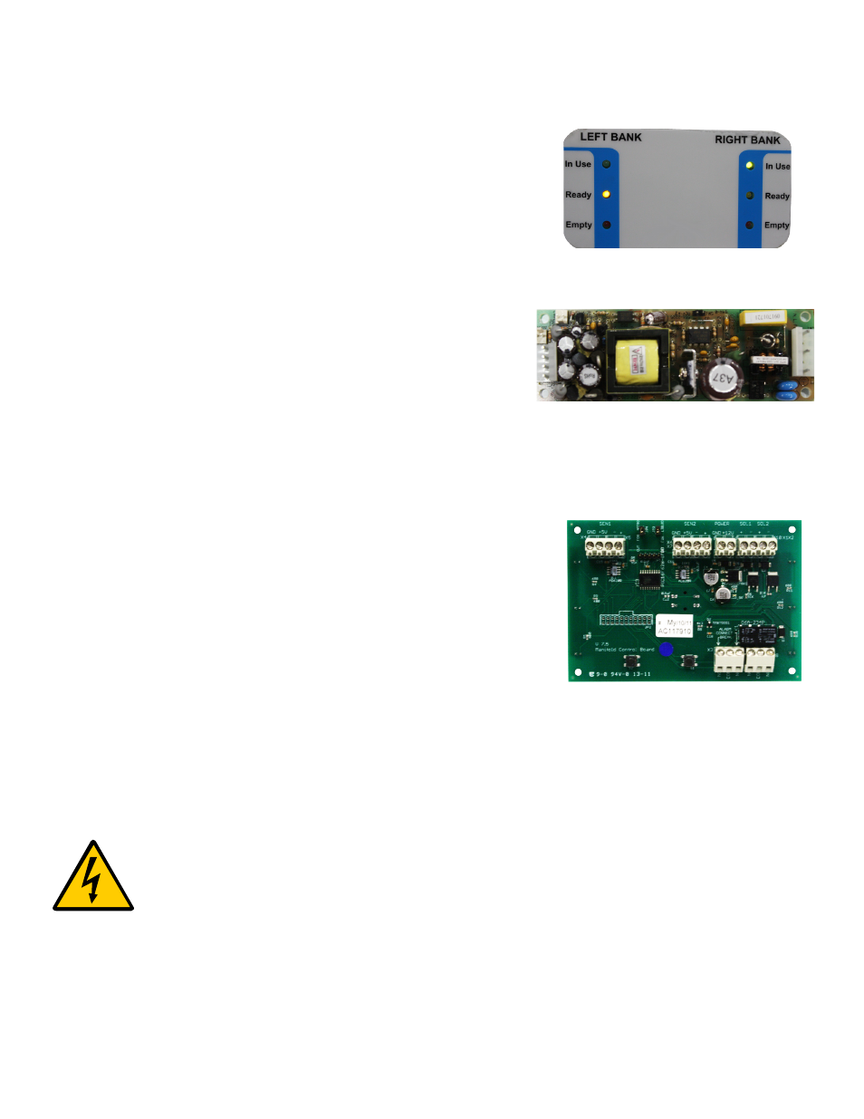
FRONT PANEL INDICATORS
Six front panel indicators monitor the status of the manifold.
POWER SUPPLY
The power supply is 110-240 VAC, 50-60 hz. It is mounted on the top
right-hand side of the manifold and is provided with a 1 amp fuse.
CONTROL BOARD
The control board is an electronic circuit board that controls the
bank switch over. It monitors the pressure with the help of the bank
transducers and controls the solenoid valve in order to initiate the bank
switch or changeover. The control board illuminates the appropriate
front panel indicators and also provides dry contacts for the activation
of a remote buzzer or external master alarm. Power to the control board
is provided by the external power supply.
Description of Parts