Description of parts – Amico Dome Loaded Manifold NFPA User Manual
Page 7
www.amico.com
7
Description of Parts
When replacement cylinders are attached to the depleted bank, the Red LED goes out and the Yellow LED illuminates
indicating that the bank has been automatically designated as the secondary supply. No other user interaction is
required. Both sets of dry contacts close to cancel any external alarm condition.
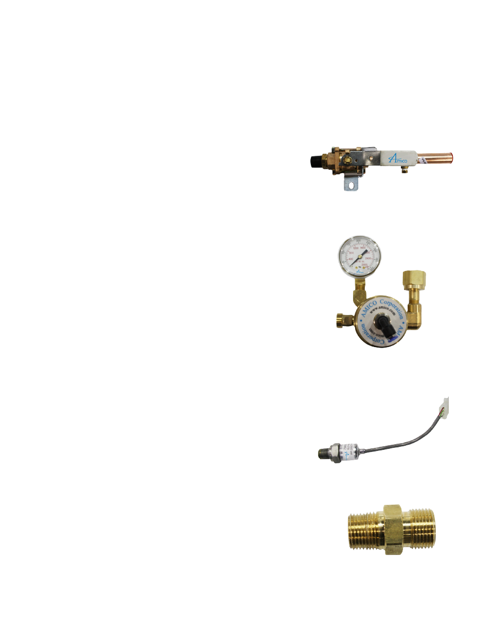
MAIN LINE SOURCE VALVE
A ¾ “ isolation valve with a locking handle, supplied with the manifold,
should be installed on top of the manifold connecting to the main supply line.
BANK REGULATOR
A dome loaded, single stage, diaphragm type regulator is used to reduce
the pressure of incoming cylinder contents to a lower intermediate pressure.
A bank regulator (one for each bank of cylinders) has an internal adjusting
spring used to set a “base” pressure of approximately 100 PSI (200 PSI on
Nitrogen manifolds). The “dome” (i.e. bonnet or bell) of the regulator is a
pressure tight chamber. When pressure is applied to the dome, the amount
of force applied is added to the force of the adjusting spring. For example,
when 55 PSI of pressure is applied to the dome, then the 100 PSI base
pressure setting is raised to approximately 155 PSI.
PRESSURE TRANSDUCERS
The pressure transducer senses the bank pressure and transfers information
to the display board to indicate the In Use, Reserve and Empty modes. There
are two transducers in the manifold cabinet, one for the left bank cylinder
and one for the right bank cylinder.
CHECK VALVE
The check valve is located upstream of each bank regulator to prevent back
flow while servicing a bank regulator.