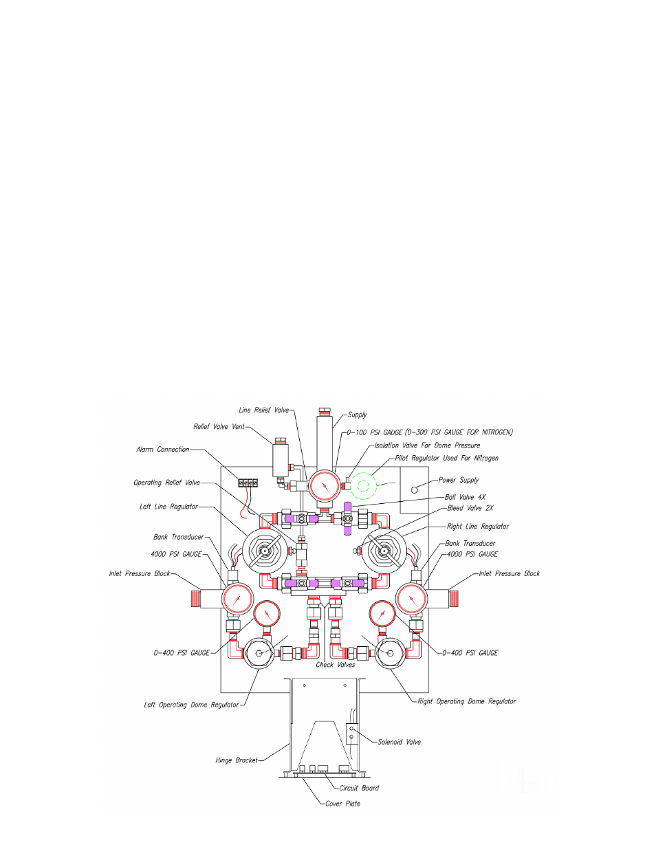
Description of parts – Amico Dome Loaded Manifold NFPA User Manual
Page 10
GAS SERVICE IDENTIFICATION
Amico manifolds are clearly labeled for the intended gas use, with the appropriate gas identified with a label that is
attached on the cabinet door. There are two pipes extending from the top of the cabinet: one is for the main line pressure
and the other is for the vent of the pressure relief valves, also labeled accordingly.
HEADER BAR CONNECTIONS
The gas-specific header bar should be attached to the Inlet block on either side of the manifold. The Inlet block is
provided with a sintered bronze filter and a “C” clip to secure it. The header should contain the proper gas connections
and all cylinder bar connections. The pigtail (hose) assemblies should comply with CGA standard B96, “Compressed Gas
Cylinder Valve Outlet and Inlet Connections.”
OPERATING ALARM SYSTEMS
The manifold control cabinet contains the required circuitry to send a dry contact signal to the alarm unit when a bank is
empty and changeover occurs. The normally closed internal circuitry is designed to alarm when there is an open circuit.
The depletion of a bank triggers a relay which renders the alarm circuit open and initiates the alarm signal.
10
Amico Pipeline
Description of Parts