Description of the manifold – Amico Dome Loaded Manifold NFPA User Manual
Page 6
6
Amico Pipeline
Description of the Manifold
SHIPMENT DETAILS
The Manifold system may be shipped in more than one carton, depending on the number of cylinder connections. The
main carton contains the following items:
• Manifold control panel (with power supply assembly)
• Wall mounting bracket (attached to manifold control panel)
• 3/4” Source shut-off valve
• Installation, Operation and Service Manual
Additional cartons may contain the appropriate number of header bars and cylinder pigtail assemblies. As standard,
header bar assemblies are configured so that cylinder inlets are on 11” centers. Cylinders may be placed in a double row
“Staggered” or single row “Straight” configuration. Cylinder inlets closest to the manifold control panel are intended for
cylinders placed directly beneath the manifold control panel. For gases other than oxygen and helium, 36” stainless steel,
flexible type pigtails are used. Oxygen and helium pigtails are rigid copper and are pre-bent to the approximate shape
for connection to the cylinders. The manifold is designed to be mounted directly to a wall.
THE MANIFOLD ENCLOSURE
The manifold enclosure contains a switch mode power supply that can handle voltage from 110-240 VAC with a built-in
fuse and terminal block. The enclosure on this manifold is NEMA-1 (general purpose applications only). This cabinet
must not be mounted outdoors.
The manifold also has a latched door that is easy to remove. The pre-assembled circuit board is located at the center of
the enclosure with a hinge mounting bracket. This design reduces installation time and eliminates the risk of improper
installation, since all the components of the manifold are connected and tested at the factory.
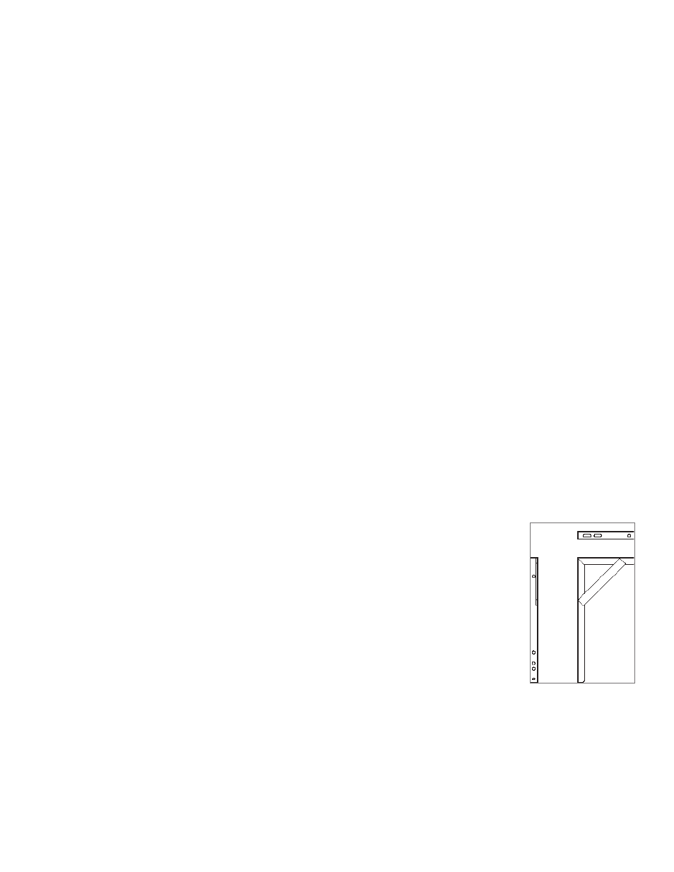
HEADER BAR WALL SUPPORT BRACKET
The manifold can support, at maximum, a 5x5 staggered header bar. While the straight header
bar contains a wall support bracket on every second pipe in between each cylinder, a standard
staggered header bar has a wall support bracket in place after every 5 cylinders, unless additional
support is requested.
MANIFOLD DISPLAY BOARD
The LED’s on the front of the Manifold indicate the status of the gas supply. The primary bank will indicate In-Use, with
the Green LED turned on, and the reserve/secondary indicating Ready, with the Yellow LED turned on, or Empty, with
the Red LED turned on depending on the status of the gas supply. When the primary bank of cylinders is depleted, the
manifold will automatically switch to the secondary bank of cylinders without interruption of gas flow to the facility. The
Red LED will illuminate when a bank is depleted and two normally closed dry contacts will open. One or both sets of
contacts may be wired to an external alarm, remote buzzer and/or a building management system.