Installation: mira led wall mount, Load data, Installing wall mount – Amico Mira LED User Manual
Page 14: Warning, Notice, 6installing triango 30 w
14
Amico Lighting Solutions
Installation: Mira LED Wall Mount
Load data
Bending moment M
B
250 Nm
Vertical weight forces FG
150 N
Installing wall mount
WARNING
To be fitted only by qualified personnel
• Installation may be carried out by a state certified
fitter. Insufficient professional knowledge could
cause life-threatening injury.
WARNING
Danger of death from electric shock.
• All-pole disconnection of the light from the
mains by an external switch must be possible.
NOTICE
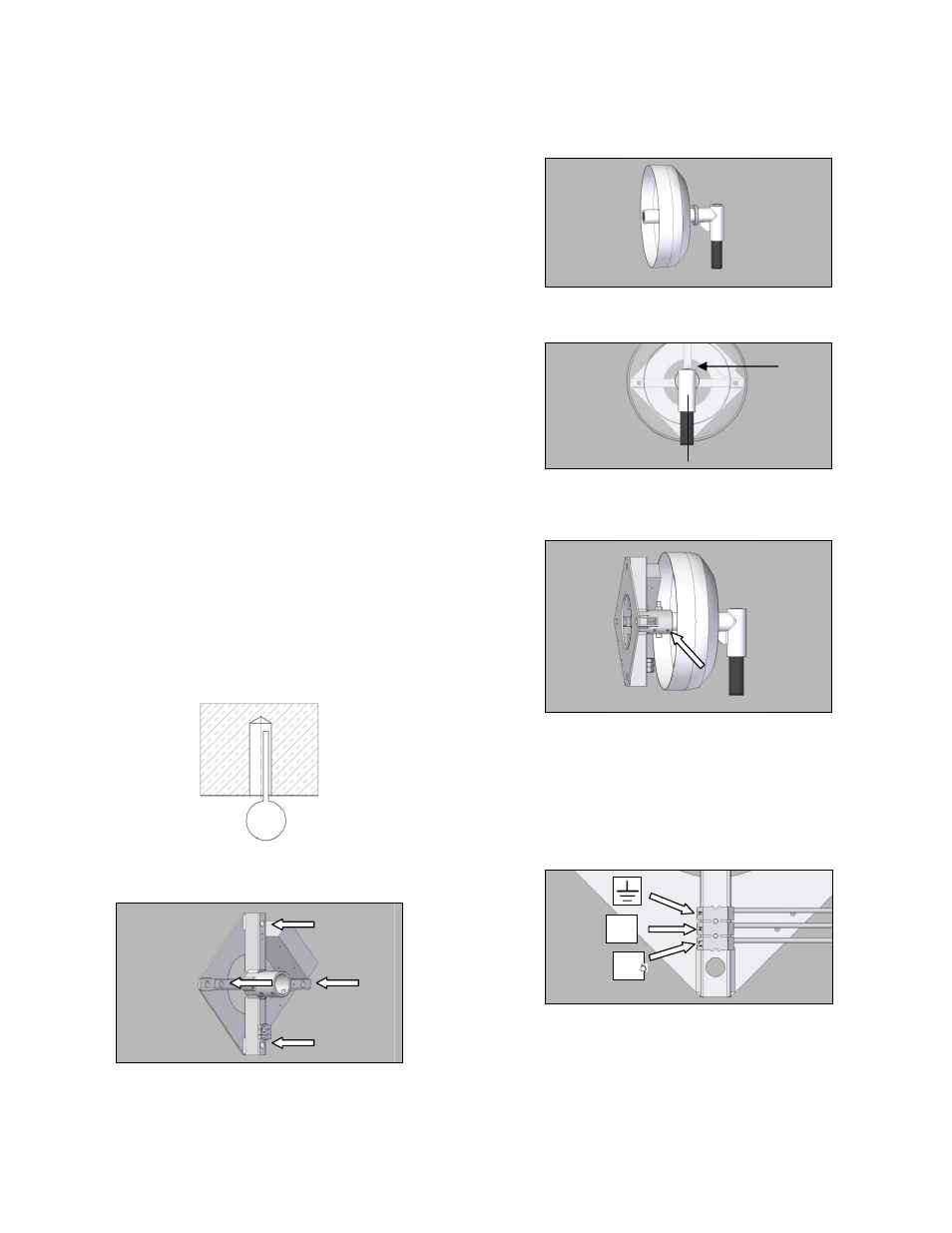
Match fasteners to load data in table.
• Note dimensions of articulation rod before
installation.
NOTICE
To observe the position.
• Orientation referred to the following Figures
• Drill holes and blow out with blower.
• Insert tubular dowels for the chosen screws and
fit the wall mount.
• Slide cover with ring on to the wall bracket.
• Attach the vertically aligned wall bracket using
M8 screw 1.
• Then tighten the 4 threaded screws.
WARNING
Danger of death from electric shock.
• Switch off circuit breaker before working on the
mains connection.
• Connect to the mains power supply.
INSTALLING triango 30 W; Installing wall mount
ENG
13
6
INSTALLING triango 30 W
6.1
Load data
Bending moment M
B
250 Nm
Vertical weight forces F
G
150 N
6.2
Installing wall mount
WARNING
To be fitted only by qualified personnel
Installation may be carried out by a state-
certified fitter. Insufficient professional
knowledge could cause life-threatening
injury.
WARNING
Danger of death from electric shock.
All-pole disconnection of the light from the
mains by an external switch must be
possible.
NOTICE
Match fasteners to load data in table.
Note dimensions of articulation rod before
installation.
NOTICE
To observe the position.
Orientation referred to the following Figures
Drill holes and blow out with blower.
Insert tubular dowels for the chosen screws
and fitt the wall mount.
Slide cover with ring on to the wall bracket.
Attach the vertically aligned wall bracket
using M8 screw 1.
Then tighten the 4 threaded screws.
WARNING
Danger of death from electric shock.
Switch off circuit breaker before working on
the mains connection.
Connect to the mains power supply.
L1
1
N