Installation: mira led ceiling mount, Load data, Installing ceiling mount – Amico Mira LED User Manual
Page 11: Warning, 5installing triango 30 c
www.amico.com
11
Installation: Mira LED Ceiling Mount
Load data
Bending moment M
B
200 Nm
Vertical weight forces FG
130 N
Installing ceiling mount
WARNING
To be fitted only by qualified personnel
• Installation may be carried out by a state certified
fitter. Insufficient professional knowledge could
cause life-threatening injury.
WARNING
Danger from falling light.
• The ceiling must be solid concrete to ensure a
secure mount.
WARNING
Danger of death from electric shock.
• All-pole disconnection of the light from the
mains by an external switch must be possible.
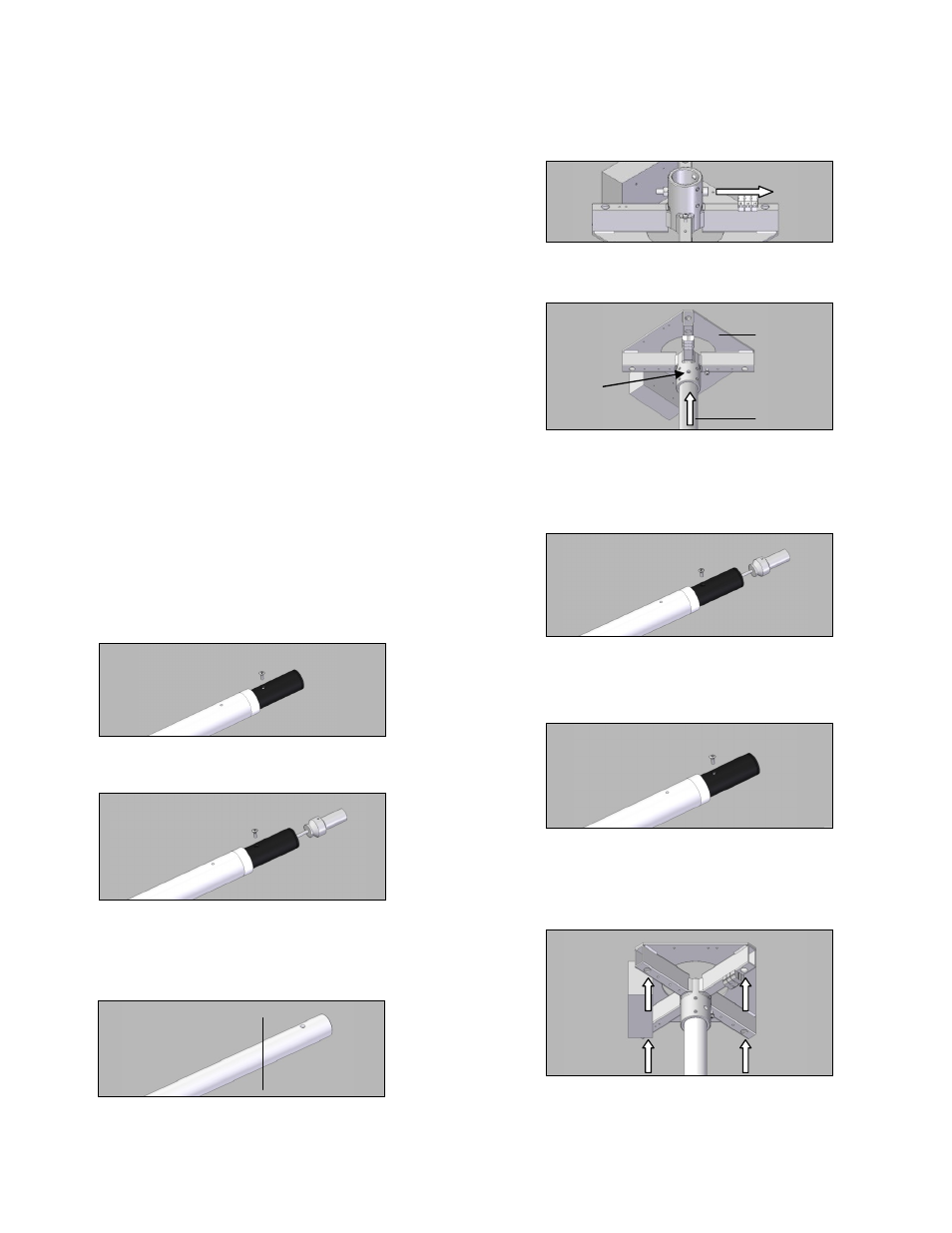
• Loosen the mounting screw from the receptacle.
• Using long-nose pliers, pull the receptacle with
cable completely out of the ceiling tube at the
inner ring.
• Cut the ceiling tube to the required length at the
upper end using a metal saw and de-burr the cut
end.
• Remove the mounting screw.
• Insert the ceiling tube 1 into the ceiling mounting
2 and drill with an Ø 9 mm bit 3. Use the existing
bore of the ceiling mounting as a guide.
• Push the cable with receptacle into the ceiling
tube again.
• Align the threaded bore in the receptacle exactly
with the existing bore in the ceiling tube. Fix with
the mounting screw.
• Mark 4 drilling points.
ENG
INSTALLING triango 30 C; Installing ceiling mount
10
5
INSTALLING triango 30 C
5.1
Load data
Bending moment M
B
200 Nm
Vertical weight forces F
G
130 N
5.2
Installing ceiling mount
WARNING
To be fitted only by qualified personnel
Installation may be carried out by a state-
certified fitter. Insufficient professional
knowledge could cause life-threatening
injury.
WARNING
Danger from falling light.
The ceiling must be solid concrete to
ensure a secure mount.
WARNING
Danger of death from electric shock.
All-pole disconnection of the light from the
mains by an external switch must be
possible.
Loosen the mounting screw from the
receptacle.
Using long-nose pliers, pull the receptacle
with cable completely out of the ceiling tube
at the inner ring.
Cut the ceiling tube to the required length at
the upper end using a metal saw and deburr
the cut end.
Remove the mounting screw.
Insert the ceiling tube 1 into the ceiling
mounting 2 and drill with an Ø 9 mm bit 3.
Use the existing bore of the ceiling mounting
as a guide.
Push the cable with receptacle into the
ceiling tube again.
Align the threaded bore in the receptacle
exactly with the existing bore in the ceiling
tube. Fix with the mounting screw.
Mark 4 drilling points.
3
1
2