Troubleshooting – Great Plains 1520P Operator Manual User Manual
Page 93
5/6/2010
118-732M
91
Veris Drive Operating Instructions
a.
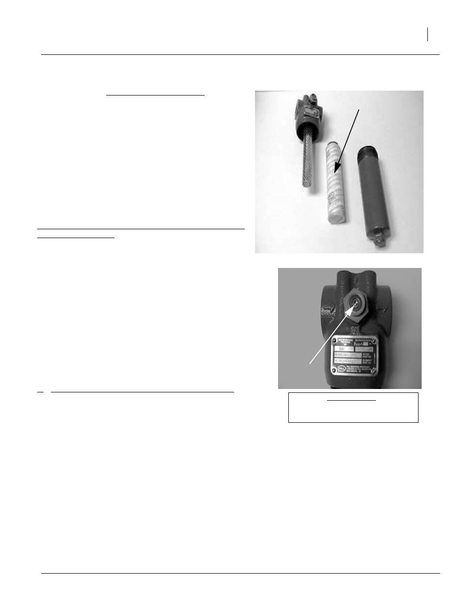
Re-set pop-out indicator if necessary.
It is a good idea to keep a filter element on hand, and we recom-
mend changing at a minimum on an annual basis.
1.
Between planting seasons, store cab console inside a rela-
tively stable and dry environment.
2.
Avoid direct spray from high pressure washers on the motor
encoder and the external controller box. These units are
sealed from normal moisture, but high pressure could inject
water into the housing.
3.
Keep electrical connects free from dirt and grease. It’s a
good idea to occasionally spray the terminals with contact
cleaner to ensure proper connection.
Troubleshooting
Drive will not rotate: (see Troubleshooting flow chart and
electronics overview)
1.
Check cab console
b.
No power to cab console - check with voltmeter.
c.
Upper line (set) is visible but no lower line (out rate and
speed) on display: move to Communication troubleshooting
below.
d.
1 or 10 amp fuse on power cable may be blown.
e.
Engage button is not on - check to see if green indicator light
is on.
f.
Use Cab Console Power Tester (PN 27857) to check power
out of cab console. Install tester on round 7 pin power/com
cable from cab console. Turn drive on. Green LED shows
power to external controller. Red LED shows power to sole-
noid. If LED lights are not lit, double-check power and con-
nections; replace cab console if needed.
2.
Check Communication between cab console and drive
a.
Check to see if power and communication cable (main harness) is
properly connected.
b.
If no lower line on cab console appears (speed and output rate),
and drive will not rotate in calibration mode, use Cable Continuity
Tester (PN 27859) to test power and communication to external controller. (WARNING: TO PREVENT DAM-
AGE TO COMPONENTS, DISCONNECT POWER/COM CABLE FROM CAB CONSOLE AND EXTERNAL
CONTROLLER BEFORE INSTALLING THIS TESTER). Install 4-pin test plug on end of 4-pin power/com
cable before powering the Cable Continuity Tester - remove before reattaching power/com cable directly to
cab console.
c.
If Cable Continuity Tester shows power is getting to external controller, turn power off and remove Cable
Continuity Tester and 4-pin test plug from ends of power/com cable. Reattach power/com cable to cab con-
sole and external controller.
d.
If power/com cable tester shows power and communication is reaching external controller from cab console,
and no lower line appears on cab console, replace chip or external controller. Call Service Department.
e.
If Cable Continuity Tester (PN 27859) isn’t available, check cable with voltmeter at connection at control
module.
Element
Pop-Out
Indicator
Figure 1 and 2.
Filter Element and Pop-Out Indicator