Install mounts & sensors, Install mounts, Install sensors – Great Plains 116-283A Installation Instructions User Manual
Page 6
6
Great Plains Manufacturing, Inc.
LOUP 2/3 CHANNEL SHAFT MONITOR
116-284M
2013-08-27
Install Mounts & Sensors
Install Mounts
Refer to Figure 9 (which is a bottom view - drill front is at the
top of the illustration)
30. Depending on feeder cup size, select three of:
(“Large”)
116-020D SMALL CUP SENSOR MOUNT
31. Select three new:
801-199C SCR SELF TAP #10 X 3/4
With the slotted-hole break of the mount (
down and to the rear, and the short break of the
mount up and to the front, secure the mount to the
seed box wall with the self-tapping screws
Note: Do not over-tighten the screws.
32. Repeat step 31 for each sensor position.
Install Sensors
33. Select one new:
253100 LOUP SHAFT SENSOR 2&3 CHANNEL
If two plastic nuts
are pre-installed, remove and
save one.
If the sensor may include a bracket not used in this
installation. Remove it.
34. If no plastic nuts
sensor
, select two new:
710425 NUT HEX JAM, PLASTIC M16 X 2
Thread one jam nut onto
35. Insert the flat faced end of the sensor
through the
slotted hole in the mount (
second jam nut
36. Check that the drive shaft is rotated so that the
magnet
face is parallel to the sensor face.
37. Adjust the jam nuts so that the gap
between the
sensor face and the magnet face is:
1
⁄
8
inch (3.2 mm)
Note: If the gap is too small, the edge of the magnet, or
the cable ties, may strike the sensor as the shaft
rotates. If the gap is too large, the sensor may fail
to detect shaft rotation.
38. Rotate the shaft to verify clearance. Set the seed
rate handle to 0 and check clearance again. Set the
seed rate handle to 100 and check clearance.
39. Tighten the jam nuts. Do not over-tighten.
40. Repeat step 33 through step 39 for each sensor
position.
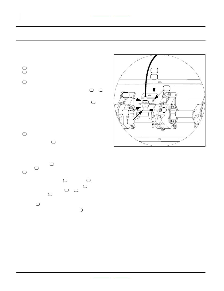
Figure 9
Mount & Sensor Install
34210
8
24
8