Identify meter type, Prepare the drill, Identify mounting positions – Great Plains 116-283A Installation Instructions User Manual
Page 2: Notes
2
Great Plains Manufacturing, Inc.
LOUP 2/3 CHANNEL SHAFT MONITOR
116-284M
2013-08-27
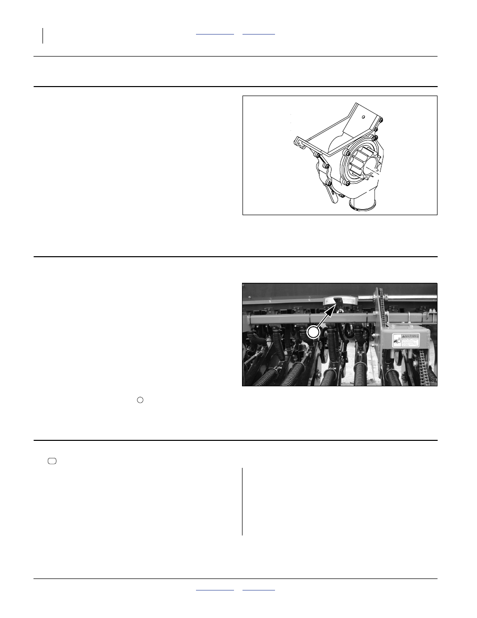
Identify Meter Type
1.
Determine whether the drill has large or small feeder
cups.
Large cups, used on most drills still in production,
have a
1
3
⁄
4
inch flute width,
and an approximate external width of
2 inches at the side walls.
Small cups, used on older drill designs have a
1
1
⁄
4
inch flute width,
and an approximate external width of
1
1
⁄
2
inches at the side walls.
Prepare the Drill
2.
Move the drill to a location with adequate lighting,
and a clear surface beneath for recovery of any
falling parts.
3.
If a folding model, unfold the drill. Consult the
Operator manual for details and safety
considerations.
4.
Raise the drill or otherwise configure it so that the
meter drive shaft may be rotated while the drill is
stationary.
5.
Install all locks or supports necessary to support the
drill while it is being worked on.
6.
Shut off any tractor used to position the drill.
7.
Set the seed rate handles
, for all main seed boxes,
to 50 on the 0-to-100 scales.
Identify Mounting Positions
8.
Select one new:
540017 MAGNET, ADHESIVE BACKED, LARGE
Do not remove the release backing at this time.
On each main seed box, use the magnet to identify
locations between cups with the following attributes:
• close to drill center, on wing boxes, cups closest to the
center box section.
• not obstructed to the front by a seed rate handle, and
• adequate exposed surface on the drive shaft to place
the magnet - or adequate length of polymer tube to
provide cuts for magnet mounting.
9.
Tag each location with a short length of tape on the seed box.
Figure 2
Meter Feeder Cup
17951
Figure 3
Set Rate Handles to 50
28066
2
Notes:
Gaps with lock collars generally provide exposed shaft.
Tube mounting requires that the tube be at least as long
as the magnet for surface mounting, and at least
1
1
⁄
2
inches longer than the magnet for cut-away
mounting (see footnote on page 4).
Smaller row spacings may require reducing magnet
length, to not less than 1
3
⁄
4
inch.