Tube install – Great Plains 116-283A Installation Instructions User Manual
Page 4
4
Great Plains Manufacturing, Inc.
LOUP 2/3 CHANNEL SHAFT MONITOR
116-284M
2013-08-27
Tube Install
If the magnet location has a bare shaft, continue at
“Shaft Face Install” on page 3.
Tube install requires that tube rotation be coupled to
shaft rotation (it is normally free to spin). There are two
ways to accomplished this. The method enumerated
below may be easier. See footnote
a
for an alternative
method.
17. De-grease and dry the spacer tube
18. Select one new:
540017 MAGNET, ADHESIVE BACKED, LARGE
19. Before removing the release backing, check that the
magnet
fits. If it does not fit, trim it as required,
keeping it longer than the minimum length specified
in the “Notes:” on page 2.
20. Aligning with the shaft center-line (and to the extent
possible, in the center of the cup-to-cup gap), outline
the magnet position with a marker. Add a vertical
mark that is approximately
3
⁄
8
inch inside each end
of the outline.
21. Brace your arm against the seed box, and rotate the
tube while holding the marker at the vertical marks.
22. On the side of the tube opposite the magnet position,
make vertical cuts on the scribed lines.
Make the cuts wide enough for the ratchet ends of
the ties
, and approximately
1
⁄
4
of the tube
circumference. Be careful to not cut the shaft. Clean
away any cutting debris.
23. Remove the backing release film from the
magnet
. Apply the adhesive side of the magnet to
the outlined area.
24. Select two new:
(These are the smaller ties)
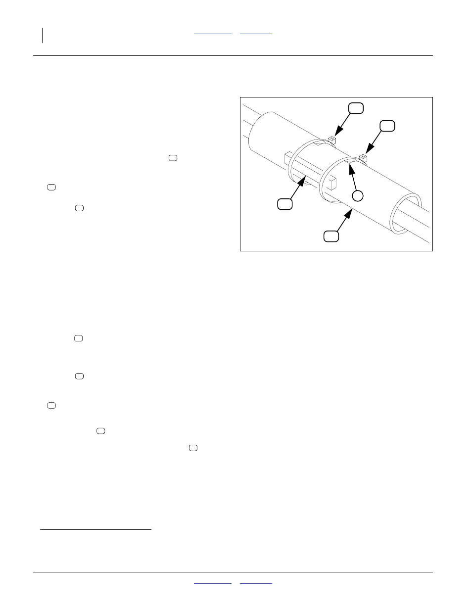
Install the ties
at each end of the magnet, so that
when finally tightened, the ratchet end of the tie will
be on the shaft face opposite the magnet
.
Tighten the ties so that they lay flat against a shaft
face in the cuts. This prevents independent tube
rotation.
25. Continue with the next magnet location at “Install
Magnets” on page 3, or if all magnets are installed,
at “Drill Mounting Holes” on page 5.
a. Cut-away Mounting: You may also cut or grind a slot in the tube, and mount the magnet directly on the shaft face, as in the
“Shaft Face Install” method. Be sure to use the cable ties to secure the magnet (ties may be tied around the tube, with or
without cuts).
Figure 6
Magnet on Tube
13198
4