Great Plains 116-283A Installation Instructions User Manual
General information, Loup shaft monitor, Installation instructions
Great Plains Manufacturing, Inc.
1
© Copyright 2012
Printed 2013-08-27
116-284M
Installation Instructions
Loup Shaft Monitor
Used with Drill models:
• Compatible with most 1995 and later two- and
three-box drills with
5
⁄
8
-inch square main seed box
meter drive shafts. Have your dealer contact the
factory if there is any question.
• Compatible with many pre-1995 drills with
5
⁄
8
-inch
square main seed box meter drive shafts. Have your
dealer contact the factory if there is any question.
General Information
These instructions explain how to install a Loup Shaft
Monitor. The kit adds a rotation sensor
seed box meter drive shaft of each drill box, and a
monitor console
in the tractor.
In operation, when the main seed box shaft of any drill
box stops rotating for more than 20 seconds, an alarm
sounds in the tractor cab.
One kit updates one entire drill:
Tools Required:
• calibration crank and/or instructions for performing a
calibration on this model drill,
• basic hand tools, including drill and tap wrench,
•
3
⁄
16
inch (#12, 4.8 mm) drill bit,
•
1
⁄
4
-20 tap, and #7 drill bit (or 5.1 mm),
• three
1
⁄
4
inch (6.3 mm) fasteners for installing the
console in the tractor cab, and
• a knife or saw capable of cutting hard rubber
(may not be required for larger row spacings).
Compatibility Check
At one drill box, inspect the shaft passing through the
main seed box feeder cups
. Verify that it is square
(not hexagonal) and is
5
⁄
8
inches on a side (15.9 mm).
The kit is compatible with bare shafts
, or shafts inside
round plastic spacer tubes
between meters. It is
compatible with large 817-075C (1
3
⁄
4
inch flute width)
1
⁄
4
inch) feeder cups.
Notations and Conventions
Call-Outs
Kits
Kit Description
116-282A
LOUP 2 CHANNEL SHAFT MONITOR
116-283A
LOUP 3 CHANNEL SHAFT MONITOR
Note: Although the kit components may be mechanically
compatible with the Small Seeds Attachment, the
kits have not been tested in that application, and
the harnesses may be too short.
Note: The kits are compatible with current single-box
drills. Only one sensor would be used. The system
ignores disconnected channels.
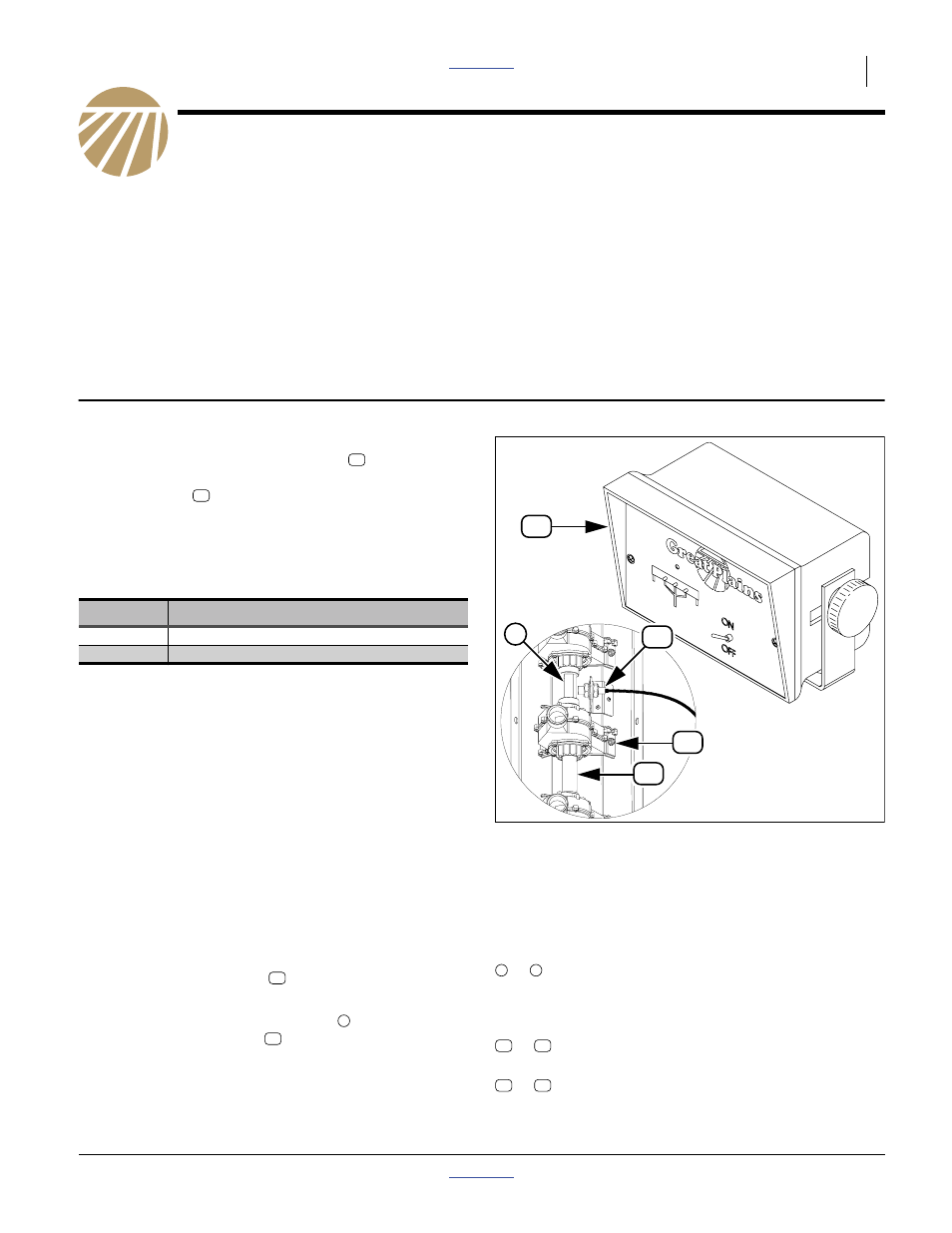
Figure 1
3 Channel Console and Sensor
18943
34210
1
to
Single-digit callouts identify components in
the currently referenced Figure. These
numbers may be reused for different items
from page to page.
to
Two-digit callouts in the range 11 to 21
reference new parts from the list on page 13.
to
Two-digit callouts in the range 51 to 55
reference existing parts.
1
9