Assembly, Assembly of tongue – Great Plains NTA1300 Predelivery Manual User Manual
Page 6
4
NTA 1000 and NTA 1300 148-528Q
7/29/2004
Great Plains Mfg., Inc.
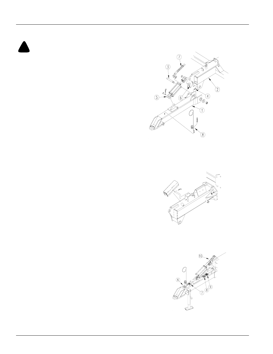
Figure 1
Tongue Assembly
Figure 2
Cylinder Lock Channel
Figure 3
Decal Placement for Tongue
Assembly of Tongue
Be sure the frames are being supported and lifted
properly. Use safety measures at all times.
Refer to Figure 1
1.
Assemble tongue (1) to CPH frame (2) by aligning the
holes in the frames and using the tongue rear cross
pin (3) with the 3” OD flat washer and 1” nylock hex
nut. Place 5/8 x 2 3/4 bolt through hole in side bushing
and cross pin. Tighten the 1” nylock nut.
2.
Assemble cylinder (5) base end to tongue frame using
1 x 2 3/4 pin clevis and hair pin cotter. Attach other end
of cylinder to CPH frame with the stroke gauge pointer
(6), pin cotter and flat washer 1 SAE.
3.
Attached the depth indicator plate (7) to the cylinder
securing it in place with 5/8 lock nuts.
4.
Place spring hose loop (8) into frame using 1/2 bolt,
flat washers and lock spring washer to secure.
Refer to Figure 2
5.
The cylinder lock channel, bent pin and pin hair cotter
are used to lock cylinder in place while drill is in trans-
port mode. While not in use, store at location indicated
below.
Refer to Figure 3
Decal placement on tongue.
6.
Decal-pic-Read Manual
7.
Decal pic- High Pressure Fluids
8.
Decal pic-Wear Eye Protection
9.
Decal pic-Do Not Ride
10. Decal-Stroke Gauge
19419
19420
19454
!
Assembly