Assembly, Opener extension, Press wheels – Great Plains NTA1300 Predelivery Manual User Manual
Page 22
20
NTA 1000 and NTA 1300 148-528Q
7/29/2004
Great Plains Mfg., Inc.
Opener Extension
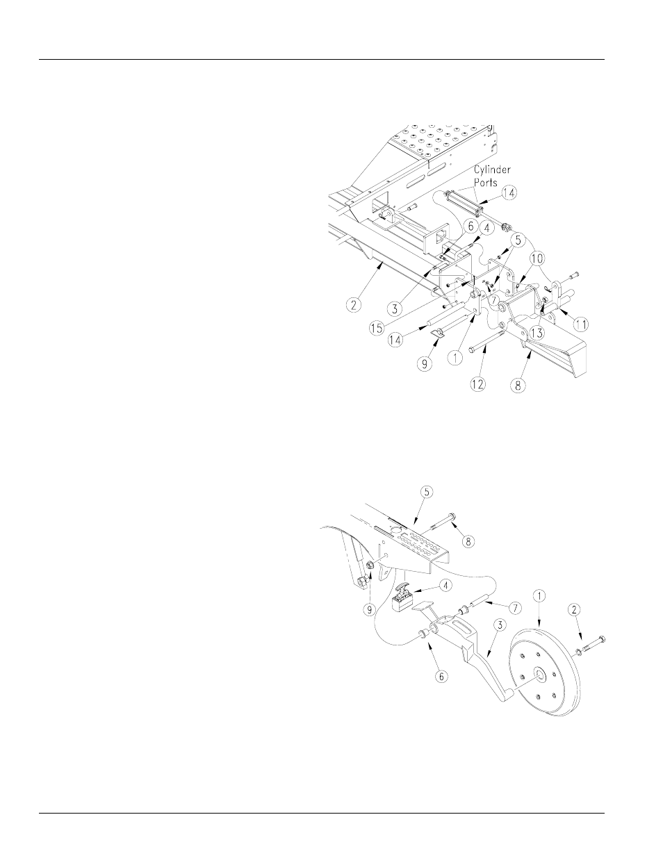
Refer to Figure 31
1.
Place opener hinge weldment (1) against end of sub-
frame (2) using a 1/2-13 x 6 1/32 x 5 1/4 u-bolt (3) on
the front tube and a 1/2-13 x 3 1/32 x 4 u-bolt (4) and
hex lock nuts (5). Insert 1/2-13 x 2” bolts (6) through
center holes with lock washer (7) and hex lock nuts
(5).
2.
Bring opener fold frame (8) up to opener hinge weld-
ment (1) aligning bottom holes. Place lock pin (9)
through holes and raise wing frame till hinge holes
align Insert the hinge pin and secure with a 5/16 x 2
1/2 bolt and lock nut.
3.
Assemble the floating lug (11), short side of the tube
to the rear of the drill, to the opener fold frame (8) with
a 1-8 x 12 1/4” bolt (12) and nylock hex nut (13).
4.
Insert cylinder (14) through the cylinder retainer, with
port holes to the rear, connecting the base end of the
cylinder to the cylinder lug on the sub-frame (2) with
pin and keeper pin. Connect the rod end of the cylin-
der to the floating lug (11) in the same manner.
Press Wheels
Refer to Figure 32
1.
Assemble press wheel (1) to pw arm (2) with a 5/8-11
x 2 1/2 bolt and lock washer (3).
2.
Install the trunnion (4) to the opener (5) by turning
handle, place through slot from underneath, and repo-
sitioning the handle to match up with the depth control
holes in the opener.
3.
Assemble bushings (6) and pivot tube (7) into pw arm.
Slide pw arm up into the opener aligning the holes and
securing in place with a 1/2-13 x 3 3/4 bolt (8) and
flange lock nut (9).
19429
19452
Figure 31
Opener Extension
Figure 32
Press Wheel Assembly
Assembly