Hydraulics, Fan hydraulics nta 1000 – Great Plains NTA1300 Predelivery Manual User Manual
Page 30
28
NTA 1000 and NTA 1300 148-528Q
7/29/2004
Great Plains Mfg., Inc.
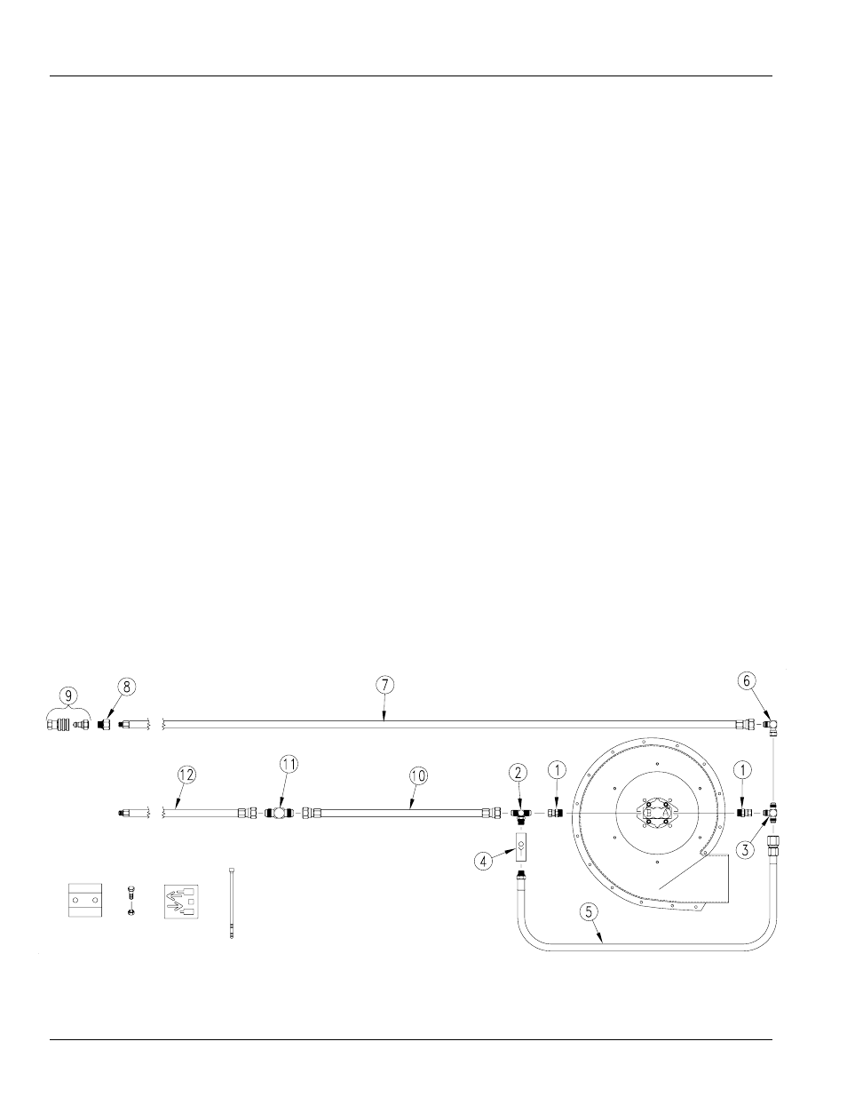
Fan Hydraulics NTA 1000
Refer to Figure 38
1.
Install 7/8MORB 3/4 FJIC adapter fittings (1) to the
ports on the fan motor. Attach 3/4MORB 3/4MJIC 3/4
MJIC tee fitting (2) to the fitting on the “B” port side of
the fan motor and the 3/4MJIC 3/4MJIC 3/4FJIC tee
fitting (3) to the fitting on the “A” port side of the fan
motor.
2.
Install one valve line check (4) to tee fitting (2) on the
bottom “B” port side of the fan motor. Check valve (4)
should be assembled with marking facing so that ori-
entation is correct with fluid flow.
3.
Assemble the 20” hydraulic hose (5) to the tee fitting
on the “A” port side and to the check valve (4) on the
“B” port side.
4.
Assemble the 3/4FJIC 3/4MJIC elbow fitting (6) to the
top of the tee fitting (3) on the “A” port side. Install the
187” hose (7) to the elbow fitting. Add the
1 1/16MORB 1/2FNPT adapter fitting (8) and the
1 1/16FORB QD coupling (9) to the hose.
5.
Route the 60” hydraulic hose (10) from the adapter fit-
ting connecting the other end to the 120” hydraulic
hose (12) using a 3/4MJIC 3/4MJIC adapter fitting
(11). Route the hoses to the tractor by way of the hose
bracket on top of the tongue.
Figure 38
Hydraulic Schematics-Fan
Hydraulics
22638