Assembly, Contact wheel cont – Great Plains NTA1300 Predelivery Manual User Manual
Page 16
14
NTA 1000 and NTA 1300 148-528Q
7/29/2004
Great Plains Mfg., Inc.
Contact Wheel cont.
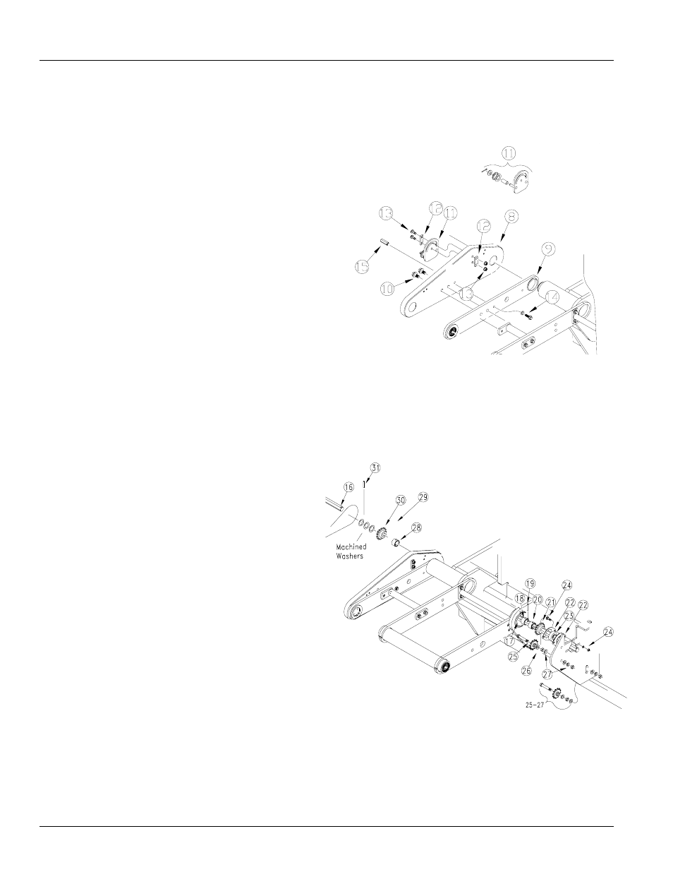
Refer to Figure 22
6.
Assemble the drive shield (8) and the arm (9) to the
contact arm (1) with 1/2-13 x 1 hex flange screws (10).
NOTE: If idler spool (11) is not assembled, assemble by
sliding on the spacer tube, 1/2 flat washer and fastening
with cotter pin.
7.
Install the idler spool assembly (11) to the drive shield
(8) placing an idler bolt plate (12) in front of the idler
spool assembly and on the outside of the drive shield.
Use 3/8-16 x 1 1/4 bolts and flange lock nuts (13).
8.
Use a 3/8-16 x 1 1/2 flange head bolt (14) and lock
washer to install the nut hex coupler (15).
Refer to figure 23
9.
Slide jack shaft (16) through bearings until the shaft
comes out the pivot bushing (17). Put the offset drive
wheel collar (18) onto the shaft. Slide collar onto shaft
until the roll pin hole is visible. Slide lock collar (20)
onto shaft first then the 7/8 hex bore sprocket (21).
10. Install one of the flangette’s (22) on the shaft followed
by the 7/8 hex bearing (23)and then the other flangette
11. Attach the flangette’s and the bearing to the frame
with 5/16-18 x 1 1/4 RHSNB bolts, lock washers and
hex nuts (24). Drive roll pin (19) through shaft on the
outside of the collar (18).
12. Install a 5/8-11 x 3 bolt (25), 42 16 T idler sprocket
(26), flat washer, hex nut and another flat washer
through the holes in the mount and tightened down
using a 5/8 flat washer, lock washer and hex nut (27).
There will be a total of two bolts with sprockets on
them.
13. Assemble the offset drive wheel collar (28) onto the
shaft along with the 42C25 7/8 sprocket (30), three
machined washers and roll pin (31).
19443
19444
Figure 22
Drive Shield
Figure 23
Drive - Jack Shaft Assembly
Assembly