Assembly, Toolbar to cph frame – Great Plains NTA1300 Predelivery Manual User Manual
Page 20
18
NTA 1000 and NTA 1300 148-528Q
7/29/2004
Great Plains Mfg., Inc.
Toolbar to CPH Frame
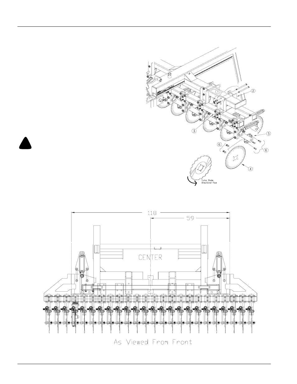
Refer to Figure 28
1.
Loosen and remove fasteners (1) from the coulter
clamp bars (2). Place toolbar (3) under CPH frame.
Reuse fasteners to hold toolbar in place. Do not tight-
en down.
Refer to Figure 29
2.
Center the toolbar assembly with the center of the
CPH frame. See figure 29 for measurements.
3.
Assemble the blades (4) to the coulter hubs (5) with
the 3/4” carriage bolts, lock washers and hex nuts (6).
NOTE: Coulter blades are set 6.35mm (1/4”) to the left of
the center of the spring bars. Account for this when locat-
ing individual coulters. If turbo blades are used on drill, be
sure they are assembled for correct rotation.
Coulter hubs and blade may spin when tightening.
19414
19451
!
Figure 28
Toolbar to CPH Frame
Figure 29
Center Toolbar
Assembly