Great Plains 3SF45 Operator Manual User Manual
Page 25
4/8/99
4-1
170-062M
DRIVE & METERING SYSTEM ADJUSTMENTS
DRIVE SYSTEM CLUTCH
Clutch Activator Engaged - Drill Raised
Fig. 17
Clutch Activator Disengaged - Drill Lowered
Fig. 18
11817
11818
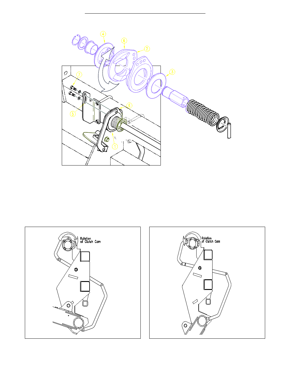
In Fig. 16 the main drive clutch (#1) on your drill is a me-
chanical release - jaw style design which may require
some adjustments before using your drill. Raise the drill
to the transport position, Fig. 17. Check between the two
cam plates (#2) which disengage the jaws (#3) & (#4) of
the clutch halves. The clutch jaws (#3) & (#4) should be
completely separated at this point.
Adjustments can be made to the cam plate (#6) by loos-
ening the bolts (#7), and nuts (#8) in the slotted box brack-
et (#5). By loosening the cam plate (#6) and rotating it
clockwise it will cause the clutch to disengage quicker and
rotating the cam plate counterclockwise will cause the
clutch to disengage slower when raising the drill.
Whenever adjusting the clutch, check to be sure the
clutch jaws (#3) & (#4) are engaged completely when the
drill is lowered to the field position, Fig. 18. The clutch
jaws (#3) & (#4) should also be completely disengaged
when the drill is raised for transport.
11882
Jaw Clutch Adjustment
Fig. 16