Install gang assembly, Gang depth indicator installation – Great Plains DVN8324 Assembly Manual User Manual
Page 26
22
8315-8324DVN
Great Plains Manufacturing, Inc.
550-466Q-ENG
11/25/2013
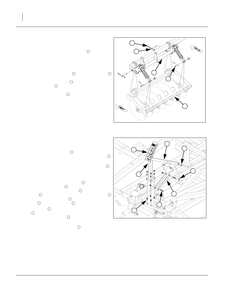
Install Gang Assembly
Note: The disc or coulter gang assemblies
will be
shipped banded together. Carefully un-band the as-
semblies. The L bundle number will be written on a
blade of each gang assembly. Refer to machine lay-
outs in “Operator’s Manual” for proper placement.
98. Carefully slide gang assembly
under gang hanger
and slowly lower machine down until front holes line
up, secure with 1 x 5 1/2 pin
, 3/8 x 2 1/4 Gr. 8, spe-
cial thread hex bolt
and 3/8 top lock nut. Slide clevis
end of gang spring bolt over rear hole of gang frame,
secure with 3/4 x 2 1/2 pin
, 3/4 flat washer and 5/32
x 1 1/2 cotter pin.
99. Torque bolts to specs.
Gang Depth Indicator Installation
100.Attach depth indicator tower
to tube of center wing
brace as shown, secure with 1/2 x 3 1/32 x 5 u-bolts
,
1/2 lock washers and 1/2 nuts.
101.Align holes on one end of the depth indicator links
(one on each side) of the lever on the gang hanger,
secure with a 1/2 x 1 1/2 hex bolt (5) and 1/2 top lock
nut. Slide bent end of depth indicator pointer (4)
through slot in depth indicator tower
. Slide other end
of depth indicator pointer
over peg on center wing
brace, secure with 1/2 flat washer
and 1/8 x 1 1/2
cotter pin
. Slide other end of depth indicator links
over depth indicator pointer
, secure with 1/2 flat
washers
, 1/2 x 1/2 hex bolt
and 1/2 top lock nut.
102.Torque u-bolts
to specs. Tighten 1/2 x 1 1/2 hex
bolts
down snug but leave loose enough to pivot.
Bend 1/8 x 1 1/2 cotter pin
over.
103.See “Depth Guide Decal Placement” on page 23 for
placement of Depth Guide Decal
.
Figure 21
Gang to Gang Hanger
41582
4
2
1
5
3
1
1
2
3
4
5
Figure 22
Gang Depth Indicator
41576
4
2
1
5
3
6
7
8
1
2
2
1
4
6
7
2
4
6
5
2
5
7
8