Install k-flex, Install magnum shank, Install k-flex install magnum shank – Great Plains DVN8324 Assembly Manual User Manual
Page 20
16
8315-8324DVN
Great Plains Manufacturing, Inc.
550-466Q-ENG
11/25/2013
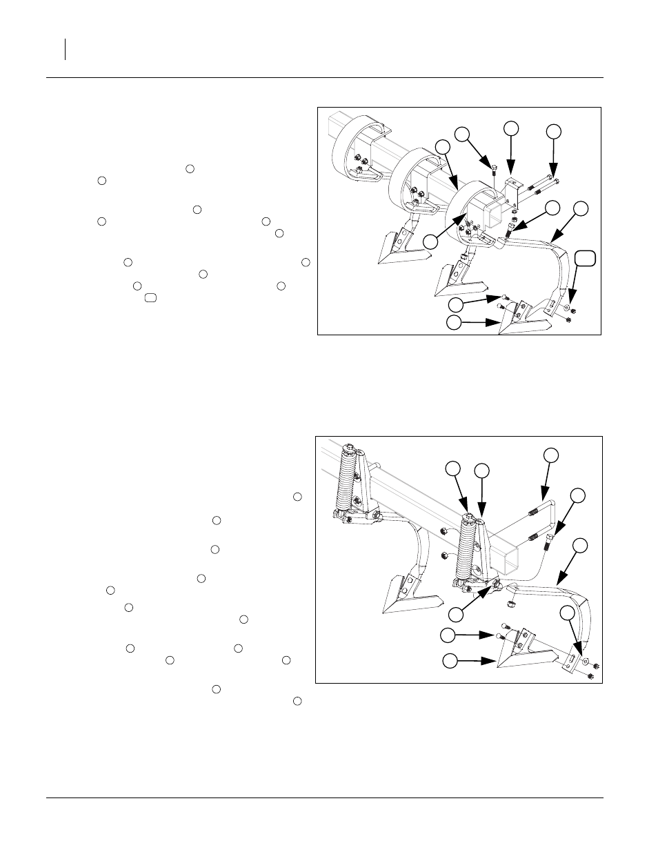
Install K-Flex
Note: See machine layouts in “Operator’s Manual” for
proper shank placement.
Refer to Figure 10
57. Slide k-flex shank mount
through slot in k-flex
clamp
. Slide these two parts over frame tube in
proper location.
58. Align top hole in k-flex clip
with top hole in k-flex
clamp
, secure with 1/2 x 1 1/2 hex bolt
, 1/2 lock
washer and 1/2 nut. Install 1/2 x 5 hex bolts
, 1/2
lock washers and 1/2 nuts.
59. Slide shank
through slotted hole in k-flex clamp
,
secure with 5/8 x 2 hex bolt
and 5/8 top lock nut.
Attach sweep
with 7/16 x 1 3/4 plow bolts
, one,
7/16 flat washer
and 7/16 nylock nuts.
60. Tighten all bolts to specs, See “Torque Values
Install Magnum Shank
Note: See machine layouts in “Operator’s Manual” for
proper shank placement.
Refer to Figure 11
61. Position pre-assembled shank mount assembly
over front of frame tube in proper location. Secure
with 5/8 x 4 1/32 x 4 3/4 u-bolt
and 5/8 top lock
nut.
62. Be sure the 3/4 nylock jam nut
is loose enough for
shank cradle to pivot.
63. Loosen 1/2 x 1 1/2 hex bolt
clear up to get 5/8 x 2
hex bolt
installed.
64. Slide shank
into shank cradle until holes are
aligned, secure with 5/8 x 2 hex bolt
and 5/8 top
lock nut.
65. Align sweep
with holes on shank
, secure with 7/
16 x 1 3/4 plow bolts
, one, 7/16 flat washer
and
7/16 nylock nuts.
66. Re-tighten 1/2 x 1 1/2 hex bolt
until threads bot-
tom out. Be sure and tighten 3/4 nylock jam nut
until threads bottom out to insure that hole doesn’t
wear excessively.
67. Tighten rest of bolts to specs, See “Torque Values
Figure 10
K-Flex Assembly
41667
8
9
6
2
7
5
3
4
1
10
1
2
3
2
4
5
6
1
7
8
9
10
Figure 11
Magnum Shank Assembly
41668
6
1
5
3
9
7
2
8
4
1
2
3
4
6
5
6
7
5
8
9
4
3