Assembly, Install center brace bar & torque tube – Great Plains DVN8324 Assembly Manual User Manual
Page 11
11/25/2013
550-466Q-ENG
Great Plains Manufacturing, Inc.
7
Assembly
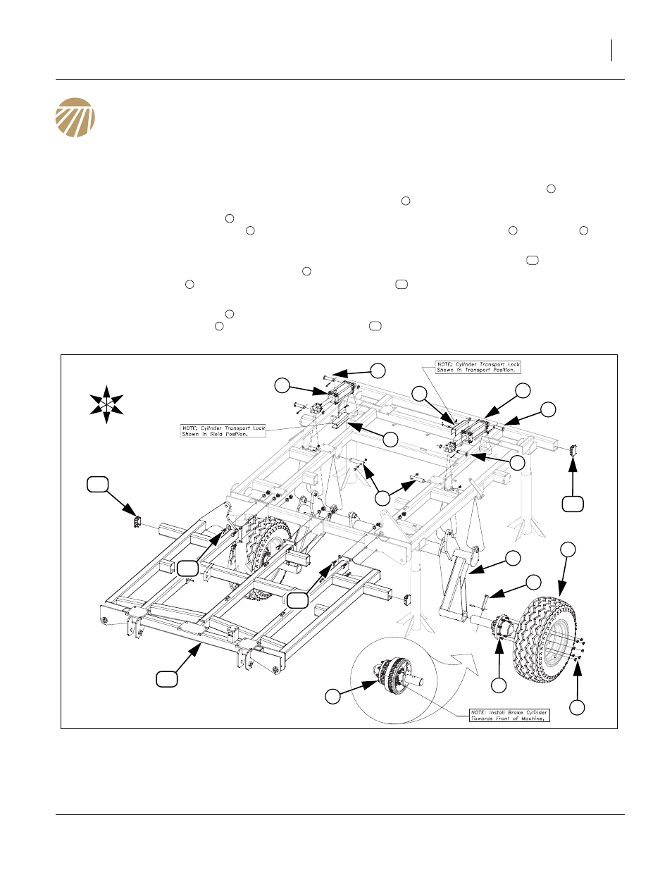
Refer to Figure 5
Install Center Brace Bar & Torque Tube
1.
Once the center Frame has been uncrated and put
on stands, the torque tube maybe installed.
2.
Carefully raise the torque tube
with an overhead
hoist and secure with 1 1/4 x 6 pins
, 3/8 x 2 1/4 Gr.
8 hex bolts and 3/8 top lock nut.
3.
Install pre-assembled hub assembly or brake hub
assembly (if machine is equipped with brakes)
,
using the 1 x 4 5/8 pin
and secure with 3/8 x 2 roll
pin.
4.
Attach the tire/wheel assembly
to hub assembly 3)
and secure with 5/8 lug nuts
.
5.
Now install 3.50 x 8 x 1.25 cylinders
using 1 x 3 1/
8 pins
, 1.5 x 1.0 x.075 machine washers and 3/16
x 2 cotter pins.
• Install cylinder transport locks
to cylinders
using
the 3/8 x 3 pins and clip pin.
6.
Carefully move center brace bar
into position with
fork truck or overhead hoist. Secure with 3/4 x 2 hex
bolts
, 3/4 lock washers and 3/4 hex nuts.
7.
All bolts may be tightened to specs, See “Torque
Values Chart” on page 37. Attach plastic end caps
to all open ends of 4 x 3 tube.
1
2
3
4
5
6
7
8
9
7
10
11
12
Figure 5
Center Brace Bar & Torque Tube
41544
U
D
F
B
L
R
7
10
8
9
4
2
3
6
5
1
4
3
8
8
9
11
12
12
11