Installation instructions, Before you start, Tools required – Great Plains 401-516A Installation Instructions User Manual
Page 7: Prepare hopper, Warning
12/28/2007
401-514M
Great Plains Manufacturing, Inc.
Installation Instructions
5
Installation Instructions
Before You Start
Most accidents are the result of negligence and care-
lessness, usually caused by failure of the operator to fol-
low simple but necessary safety precautions. Allow no
one to install the pressure relief kit before carefully read-
ing this manual.
Some fasteners may be loosely assembled. Remove
them before mounting that component. Due to evolving
manufacturing practices, some assemblies may already
be completely pre-assembled. If so, check that fasteners
are tight, and skip the unneeded assembly steps.
Tools Required
• Basic hand tools, including a center punch and a fine
tip indelible marker
• Portable drill with a
1
⁄
2
in (12mm) chuck
• Twist drill bits of sizes:
Bolt hole: 0.41in,
13
⁄
32
in, Z, or 10.1mm
Pilot hole: approx. 0.13in,
1
⁄
8
in, #31, or 3.0mm
• Measuring square
• Silicone sealant
• Blocks of supports for hopper
• Ladder
Torque values for fasteners are shown on page 15.
1.
Read and understand “Important Safety Informa-
tion” starting on page 1.
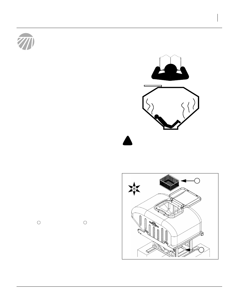
Prepare Hopper
Empty the hopper per the clean-out instructions in
your Operator Manual. Remove the strainer bas-
ket(s)
and leave the slide gate
open.
3.
From the walkboard (or a lift, if the hopper is dis-
mounted), thoroughly pressure wash the inside of
the hopper.
4.
Allow the hopper to drain and dry.
+
!
WARNING
Possible Confined Space Hazard. Do not enter hopper.
The instructions in this manual do not require hopper entry.
A hopper that has been used may represent a Confined Space
Hazard, due to low oxygen, high dust and/or chemical fumes.
Figure 2:
Prepare Hopper
27354
1
2
U
D
L
R
B
F