Install 150 bu upper components, Mark holes for drilling, Ud b f – Great Plains 401-516A Installation Instructions User Manual
Page 14
12
YP Pressure Relief Kits
Great Plains Manufacturing, Inc.
401-514M
12/28/2007
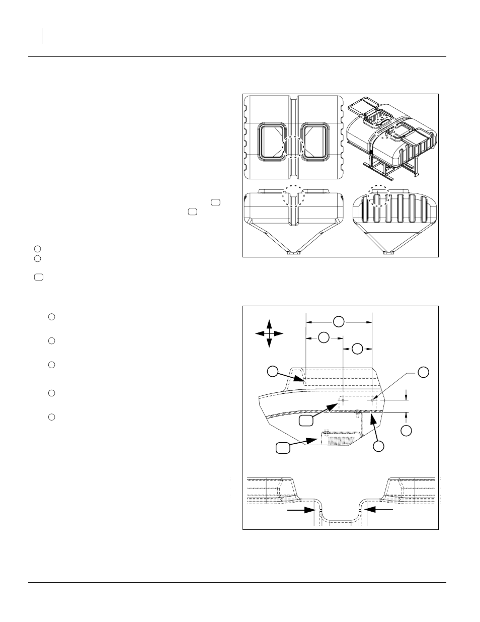
Install 150 bu Upper Components
If you are updating an 82bu hopper, use the instructions
at “Install 82 bu Upper Components” on page 10.
Refer to Figure 14
In the 150 bu hopper, the upper tube support mounts to
the stiffener rib molded into the hopper. Four holes, two
each side, need to be drilled.
This work is most easily accomplished from the walk-
board, while the hopper is on the planter.
which depicts a view from the right side above a view from
the rear. The eventual location of top tube support
is
shown in dotted line, and the angle bracket
shown in
dashed line.
Hole locations are in the side walls of the center stiffener
rib. Measurements are referenced from:
front face, rear lip of tank top openings
underside of center stiffener rib
After installation, the bottom edge of the angle bracket
is flush with the underside of the center stiffener rib.
Mark Holes for Drilling
45. Holes are above the underside of center stiffener rib:
2.28in, 2
9
⁄
32
in, 5.79cm
46. The rear holes are located forward of the lip at:
7.02in, 7
1
⁄
64
in, 17.82cm
47. The front holes are forward of the rear holes by:
5.50in, 5
1
⁄
2
in, 13.97cm
For reference, the total distance from the lip to the
forward holes is:
12.52in, 12
33
⁄
64
in, 31.79cm
48. Mark the hole centers. Hole diameter is:
0.41in,
13
⁄
32
in, 10.4mm
49. Use a 16in (41cm) straight edge to mark a line
between the hole centers, and about 2in (5cm) on
either side.
Note: Depending on the hopper and part tolerances,
these may not be the final hole positions. The final
holes are marked and drilled beginning at step 53.
Figure 14:
150 bu Hopper Drill Region
27359
Figure 15: Side / Rear View
150 bu Drill Holes
27360
U
D
B
F
B
C
H
E
1
2
A