Install 82 bu upper components, Remove support for drilling, Mark holes and drill – Great Plains 401-516A Installation Instructions User Manual
Page 12: Remove support for drilling mark holes and drill, Fb latch, Hinge
10
YP Pressure Relief Kits
Great Plains Manufacturing, Inc.
401-514M
12/28/2007
Install 82 bu Upper Components
If you are updating a 150 bu hopper, use the instructions
at “Install 150 bu Upper Components” on page 12.
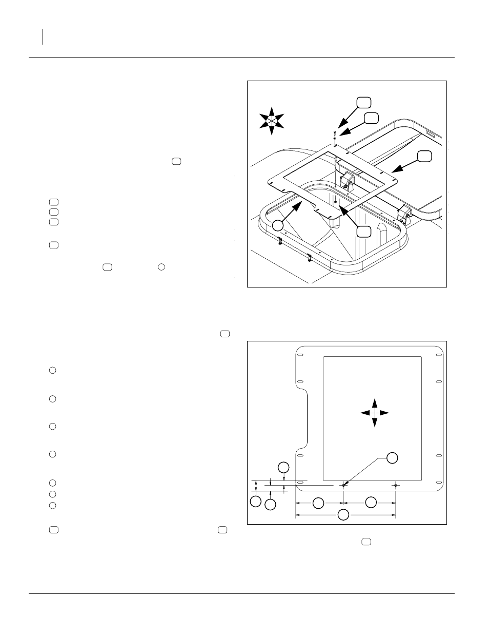
Remove Support for Drilling
Refer to Figure 10
The new upper pipe support for an 82 bu hopper mounts
on the existing strainer basket support
mally will not already have holes for this purpose. Follow
step 32 through step 38 to prepare the support.
32. Remove and save eight sets of:
802-005C HHCS 1/4-20X1 GR5
804-007C WASHER FLAT 1/4 SAE PLT
803-230C NUT HEX FLANGE 1/4-20 PLT
33. Remove the:
403-332D HOPPER STRAINER BASKET SUP-
Note: The support
has a notch
, which must be on
the latch side of the hopper opening. The latch is:
on the left for a 403-143K 82bu hopper,
on the right for a 403-226K 82 bu hopper, and:
toward the center for a 403-174K 150bu hopper.
Mark Holes and Drill
34. Mark holes on the back span of strainer support
at the following dimensions:
Latch-side edge to latch-side hole:
8.25in, 8
1
⁄
4
in, 20.96cm
Latch-side hole to hinge-side hole:
9.00in, 22.86cm
Rear edge to hole center-line
1.00in, 2.54cm
Hole diameter is:
0.41in,
13
⁄
32
in, 10.4mm
Alternate reference dimensions:
17.25in, 17
1
⁄
4
in, 43.82cm (L. edge to L. hole)
1.81in, 1
13
⁄
16
in, 4.60cm (back span width)
0.81in,
13
⁄
16
in, 2.06cm (inside to hole c/l)
35. Check hole marking with (not shown):
403-407D BRACKET (part of upper support
36. Drill pilot holes, then final holes.
Figure 10:
Remove Strainer Support
27382
U
D
L
R
B
F
1
Figure 11:
Strainer Support
Holes
27381
F
B
Latch
A
B
D
E
C
F
H
Hinge
D
E
F