Install new door slide – Great Plains 401-516A Installation Instructions User Manual
Page 10
8
YP Pressure Relief Kits
Great Plains Manufacturing, Inc.
401-514M
12/28/2007
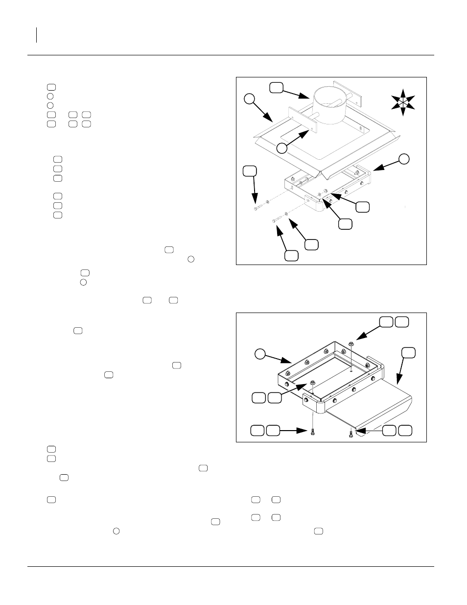
Refer to Figure 6, which depicts (top to bottom):
the new weldment,
the water guard,
the door slide assembly with
, 2x
,
forward fasteners and
, 2x
,
rear fasteners.
12. Remove and save the side fasteners in the door
guide assembly. This is:
two sets forward:
1
802-167C HHCS 1/4-20X1 1/2 GR5
1
803-088C NUT HEX LOCK 1/4-20 FLG
2
804-007C WASHER FLAT 1/4 SAE PLT
two sets rear:
1
802-370C HHCS 1/4-20X1 3/4 GR5
1
803-088C NUT HEX LOCK 1/4-20 FLG
2
804-007C WASHER FLAT 1/4 SAE PLT
Note: Remove only the side fasteners, and no fasteners
on the front or rear faces of the door slide frame.
13. Orient the lower air pipe weldment
as necessary
to pass it up through the door slide frame
.
14. Re-orient
top-Up/tilt-Back as shown, and align
the holes
on the bracket bar with the holes in the
water guard and door slide frame. Hold it temporarily
with the four removed bolts (
15. Check that the correct bolts are in their proper holes
(longer bolts to Back). Remove each bolt. Place a flat
washer
on it.
16. Apply silicone sealant to the washer and underside
of bolt head.
17. Re-insert bolt. Add a second washer
frame, and a nut
Install New Door Slide
Note that either bolt may be used in either hole,
and either nut may be used on either bolt.
18. Select one set new:
802-004C HHCS 1/4-20X3/4 GR5
803-088C NUT HEX LOCK 1/4-20 FLG
Note that these are identical to the saved bolt
and
nut
removed in step 9.
19. Select one new:
403-234D BULK HOPPER UNLOAD DOOR
(new, with two stop bolt holes)
20. With the bent lip down, insert the new door slide
into the door frame
about halfway.
21. Insert a
or
each stop bolt hole from below, and secure it with a
or
22. Pull the door slide
fully open so that any debris
from later steps can fall out of the hopper.
Figure 6:
Lower Hopper Components
27355
3
U
D
L
R
B
F
4
4
Figure 7:
Install New Door Slide
27377
2