Marker adjustments – Great Plains 3000 Operator Manual User Manual
Page 20
18
Section 3 Adjustments
2700 and 3000 Three-Point Drill 118-365M-A
9/9/10
Great Plains Mfg., Inc.
Marker Adjustments
Chain Adjustment
There are two chain adjustments. These adjustments are
interrelated and should be done in the following order. Re-
fer to Figure 3-14.
1.
Lifting Slack. Start with the marker unfolded. Back the
full-threaded adjustment bolt (1) down until the head
extends as little as possible. Slowly fold the marker, ob-
serving the motion of the disk. If the disk slides across
the ground more than about a foot before the chain and
linkage lifts it up, the chain is too long. Shorten the
chain by moving the clevis (2) in one or two links. Check
the adjustment by repeating the folding process.
If the chain is too short when the marker is unfolded, it
will prevent the end of the marker from dropping into
field depressions. Correct this condition by moving the
clevis (2) one or two links toward the end of the chain
to make it longer.
2.
Folding Slack. After completing the adjustment in step
one, fold the marker. Extend the full-threaded adjust-
ment bolt (1) until the slack is out of the chain. Lock the
bolt in this position by tightening the nuts (3) on either
side of upright channel (4).
Figure 3-14
Marker Chain Adjustment
15669
Disk Adjustment
The field mark left by the marker disk may be changed by
adjusting disk angle or direction of cut.
Disk Angle. Refer to Figure 3-15. To change the angle of
cut loosen the two 1/2-inch bolts holding the disk assem-
bly. Rotate the disk assembly as desired.
Figure 3-15
Disk Angle
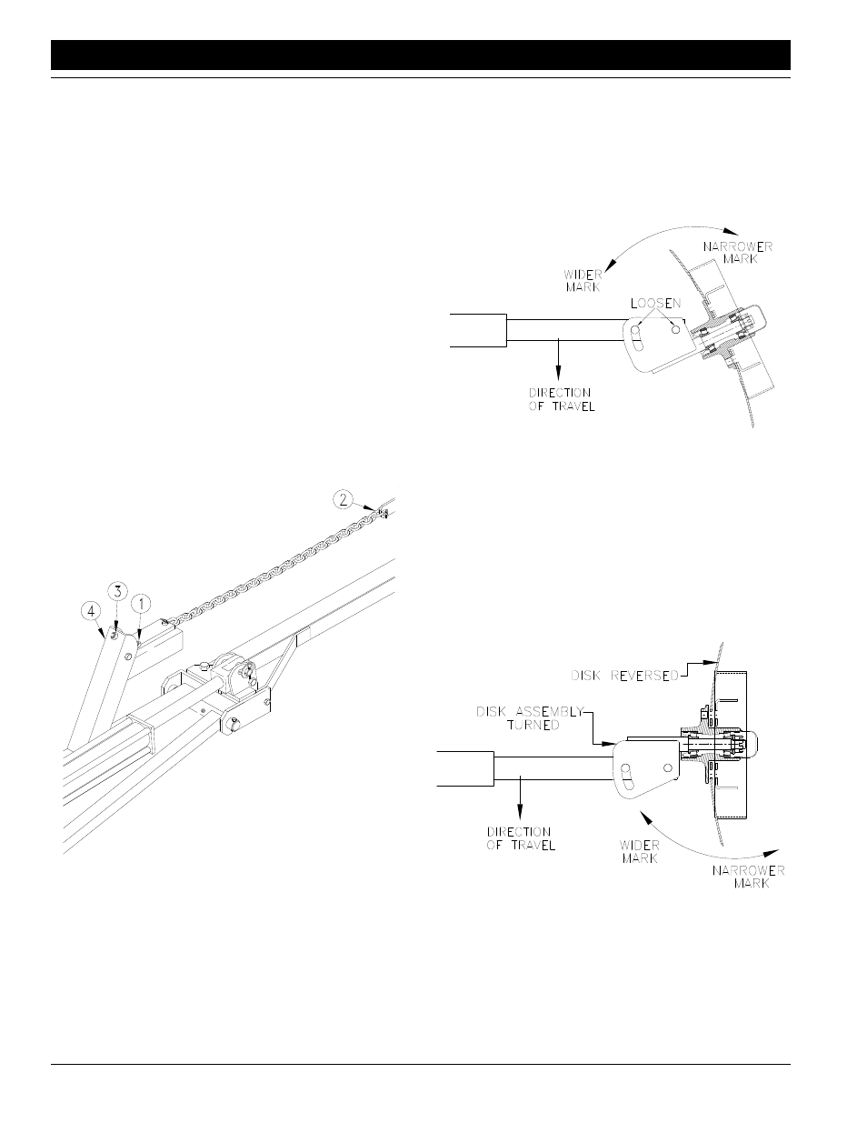
Direction of Cut. The disk may be mounted to throw dirt in
or out for different marks in different soil conditions. Refer
to Figure 3-16. To change the direction of cut:
1.
Reverse the disk by removing the four lug bolts on the
disk hub. Remount the depth band and lug bolts.
2.
Turn the entire disk assembly by removing the two 1/2-
inch bolts and turning the assembly one-half turn. Re-
install the 1/2-inch bolts and set the disk angle as de-
sired.
Figure 3-16
Direction of Cut Reversed
11757
16403