Hydraulic circuit connections, Hydraulic control overview – Great Plains NTA3010 Operator Manual User Manual
Page 19
Great Plains Manufacturing, Inc.
Preparation and Setup
15
2014-03-26
160-219M-A
Hydraulic Circuit Connections
The drill has two or three hydraulic circuits (with a low
pressure sump return line). The standard circuits power
lift, fold and weight-transfer functions. An optional circuit
operates the markers.
Great Plains hydraulic hoses are color coded to help you
hookup hoses to your cart outlets. Hoses that go to the
same remote valve are marked with the same color.
1.
Shut down tractor hydraulics.
2.
Connect either (orange) Marker hose to
receptacles
and
in any order.
3.
Connect the Retract/rod-end hose of the (blue)
Lower pair to receptacle
.
Connect the Extend/base-end hose of the (blue)
Lift pair to receptacle
4.
Connect the Retract/rod-end hose of the (yellow)
Fold pair to receptacle
.
Connect the Extend/base-end hose of the (yellow)
Unfold pair to receptacle
.
5.
Connect the sump hose to receptacle
.
6.
Check hose routing to ensure adequate slack for link
arm movement, and clearance from pinching or
abrading cart/drill components.
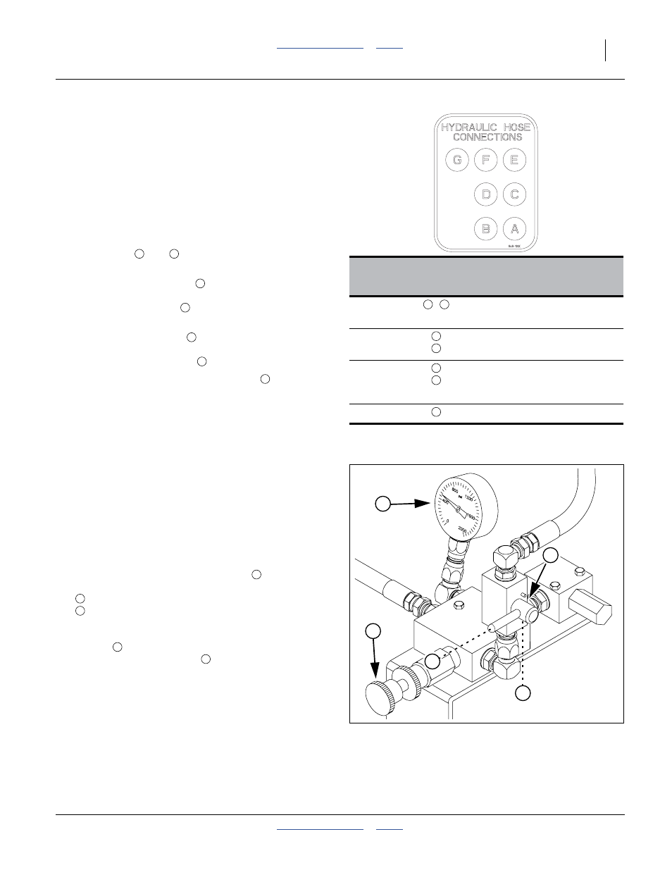
Hydraulic Control Overview
Lift/lower is on a dedicated circuit and is affected only by
tractor controls.
The other two circuits on the drill are affected by one
valve on the drill and one or two on the air cart, in
addition to the lever handles in the tractor.
Refer to Figure 9
1.
Fold/unfold has a two-position valve
on the drill
that switches between:
Transport (fold/unfold), handle horizontal and
Field (weight transfer), handle down
modes.
A knob
at the valve adjusts weight transfer when
in Field mode. The gauge
displays weight-transfer
system PSI.
Color
Cart
Ports
Hydraulic Function
Orange
,
Markers
(also used for Auger on cart)
Blue
Lower
Lift
Yellow
Fold
Unfold and Weight Transfer
(also used for Fan on cart)
No Color
Sump return
A
B
C
D
E
F
G
A
B
C
D
E
F
G
Figure 9
Fold/Weight Control Valve
26413
1
2
3
4
5
1
2
3
4
5