Install new drive, Install mount, Install pump – Great Plains YP Fertilizer Ground Drive Update User Manual
Page 6: Install inlet elbow, Mount pump, Install driven sprocket
6
Great Plains Manufacturing, Inc.
Ground Drive Update
407-630M
04/11/2011
Install New Drive
Install Mount
Refer to Figure 8
31. Select two saved:
806-102C U-BOLT 3/4-10 CORNER 7 SQ
and four sets saved:
804-023C WASHER LOCK SPRING 3/4 PLT
804-025C WASHER FLAT 3/4 SAE PLT
32. Hoist the drive mount
marks made at step 14. Insert the U-bolts
above front. Add the flat washers
washers
and nuts
33. Adjust alignment of mount to match marks. Tighten
nuts to Grade 5 torque specification in an alternating
sequence, to ensure U-bolts are evenly seated and
drive is straight front-to-back.
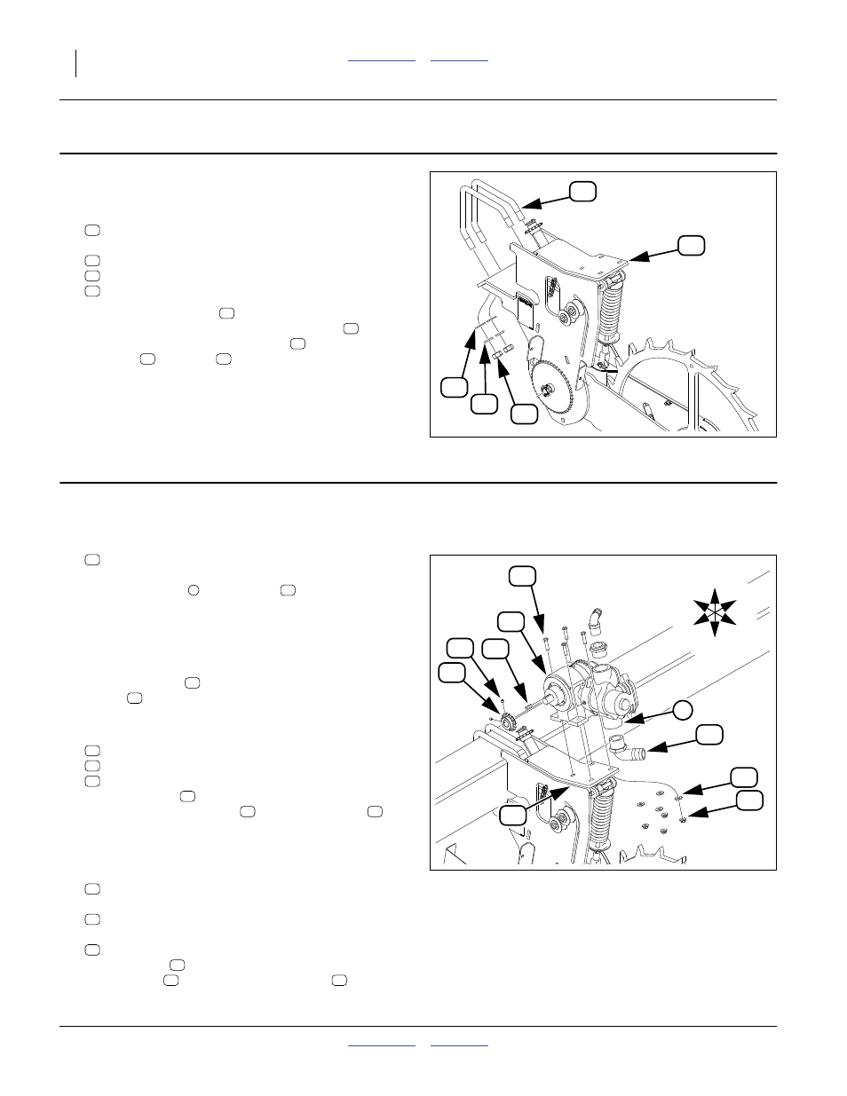
Install Pump
Install Inlet Elbow
Refer to Figure 9
34. Select one new:
830-133C EL 1 1/2MNPT X 1 1/2HB POLYP
Clean any previous sealant or other debris from the
lower (inlet) port
of the pump
PTFE pipe sealant to the threads of the elbow.
Screw the elbow into the pump port. Match the orien-
tation of the inlet elbow removed at step 12.
Mount Pump
35. Place the pump
on the top platform of the
mount
, with the inlet and outlet ports to planter
rear.
36. Select four sets new:
802-022C HHCS 3/8-16X1 1/2 GR5
804-011C WASHER FLAT 3/8 USS PLT
803-086C NUT MAC-LOK FLG 3/8-16 GR F
Insert the bolts
above. Add a flat washer
and the lock nuts
Tighten to Grade 5 torque specification.
Install Driven Sprocket
37. Select one new:
407-469H SPKT 40C15 1 ID X 1.13 KW/2SS
which includes one:
and two:
801-231C SCR SET SKT KCP 5/16-18X5/16NY
Place the key
in the pump drive shaft keyway. Add
the sprocket
Null4
Figure 8
Install Drive
32112
60
Null4
Figure 9
Install Pump
32113
1
U
D
L
R
B
F
74
22