Sys infor and diagnostics, Operator’s manual, Diagnostics – Great Plains DICKEY-john IntelliAg Planter-Drill Control L1 User Manual
Page 15
OPERATOR’S MANUAL
IntelliAg PDC User Level 1 (GP)
11001-1508-200903
SYS INFOR AND DIAGNOSTICS / 13
SYS INFOR AND DIAGNOSTICS
In order to view the following information and diagnostics screens, the
master switch must be set to the OFF position.
DIAGNOSTICS
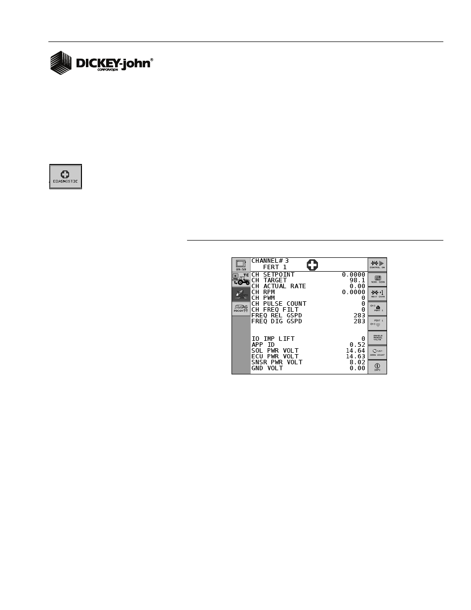
The Diagnostics screen provides various information from feedback
sensors, valve output, and system voltages of the WSMT module. The
control valve can be manually opened on this screen when necessary.
Each channel has its own Diagnostics screen. None of the items on the
screen can be edited. However the Channel Pulse Count data can be reset.
The system may be active while the Diagnostic screen is displayed.
Press the Diagnostics button to access the Diagnostics screen.
Figure 7
Diagnostics Screen
CH SETPOINT
The Channel Setpoint value is calculated by the system. It displays the
expected feedback frequency of the application rate sensor or flowmeter
used for that channel’s feedback.
CH TARGET
The Channel Target value is the current channel’s rate as entered into the
Target Rate constant on the Channel Configuration screen.
CH ACTUAL RATE
The Channel Actual Rate value is the current channel’s actual controlled
rate with the system active.