Install breakaway (2nd) section, Install third section – Great Plains 2525P Assembly Instructions User Manual
Page 4
4
Great Plains Manufacturing, Inc.
25-Foot Marker Option
113-786M
2013-09-05
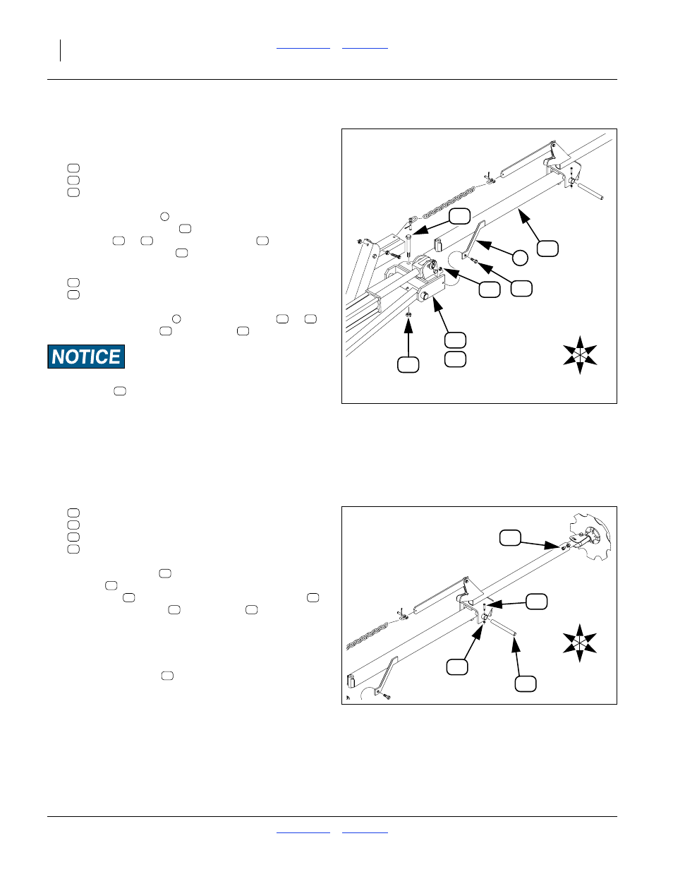
Install Breakaway (2nd) Section
Start with the left side (LH parts).
Select one each new:
113-195H 3 SECTION MARKER BREAKAWAY
802-254C HHCS 5/8-11X5 1/2 GR5
803-024C NUT LOCK 5/8-11 PLT
With the shear bar
to front, align the pivot hole of
the breakaway section
with the holes in the lug
channel (
or
). Insert the pivot bolt
. Secure to
snug with the lock nut
.
10. Select one each new:
802-266C HHCS 3/8-16X2 GR2
803-013C NUT LOCK 3/8-16 PLT
Secure the shear bar
to the lug channel (
or
)
with the shear bolt
and lock nut
.
Equipment Damage Risk:
The shear bolt
is designed to fail if the marker arm
encounters a field obstruction. Replace it only with another
3
⁄
8
-16 Grade 2 bolt. Using a lower grade causes nuisance
shears. Using a higher grade can cause equipment damage.
11. Repeat step 9 and step 10 for the right hand marker.
Install Third Section
Refer to Figure 5
12. Select one each new:
113-183H 30’F.F. MKR. 3RD. SECTION
113-311D HINGE PIN
802-115C HHCS 5/16-18X2 GR5
803-011C NUT LOCK 5/16-18 PLT
With the chain bar
on top, align the third
section
pivot bushings with the outer
breakaway
pivot bushings. Insert the pivot pin
and secure with bolt
and lock nut
.
13. Consult the Operator manual for marker extension
dimensions for your implement model, row spacing
and active row pattern.
Loosen set screws
. Adjust outer market tube
position in third section for desired extension. Secure
set screws. Rest marker on ground for step 15.
14. Lubricate the assembled pivot. There is a grease
zerk at the outer end of the breakaway section.
Pump grease until it emerges.
U
D
I
O
F
B
15
51
60
3
11
14
53
56
Figure 4
Install LH Breakaway (2nd) Section
19207
15
51
60
15
11
14
51
60
53
56
11
14
53
56
53
U
D
I
O
F
B
48
55
18
43
Figure 5
Install LH Third Section
19207
12
18
48
55
21
12
15
18
48
55
43