Prepare the implement, Mechanical assembly, Install first sections – Great Plains 2525P Assembly Instructions User Manual
Page 3
Prepare the Implement
Great Plains Manufacturing, Inc.
3
2013-09-05
113-786M
Prepare the Implement
1.
Move the implement to a spacious location with
adequate lighting, and a clear surface beneath for
recovery of any falling parts.
Choose an area suitable for full marker arm
extension and fold. This requires at least
13 feet (4 m) clearance on either side, and at least
17 feet (5.2 m) vertically.
2.
Lower the implement, Use any stands provided to
prevent tipping.
3.
Shut off the tractor. Remove the key.
Mechanical Assembly
Install First Sections
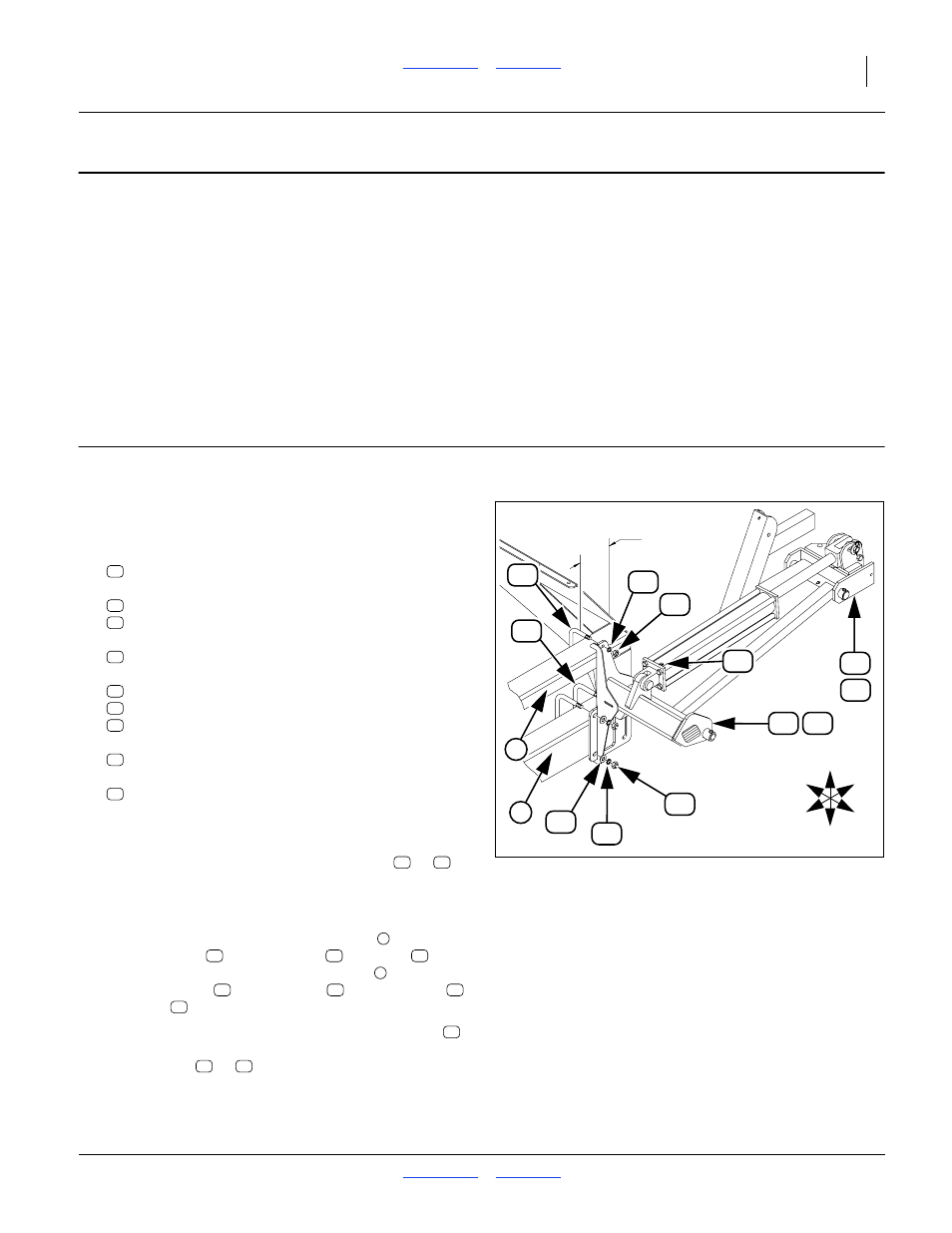
Start with the left wing (LH parts).
Select one new:
806-122C U-BOLT 1/2-13 X 3 1/32 X 6
two sets new:
804-015C WASHER LOCK SPRING 1/2 PLT
803-020C NUT HEX 1/2-13 PLT
two new:
806-053C U-BOLT 5/8-11 X 7 1/32 X 6 1/2
four sets new:
804-021C WASHER FLAT 5/8 SAE PLT
804-022C WASHER LOCK SPRING 5/8 PLT
803-021C NUT HEX 5/8-11 PLT
and, depending on side, one of:
113-781H 2520P MARKER MOUNT LH
or
113-782H 2520P MARKER MOUNT RH
Note: The mount/section assembly may have the arm
section upright when mounted.
5.
Use the lift or hoist to position the mount (
or
)
forward of the front tool bars, approximately
12.5 inches (32 cm) from the outside end of the
implement.
6.
Secure the mount to the upper tool bar
1
⁄
2
inch U-bolt
, lock washers
and nuts
.
Secure the mount to the lower tool bar
5
⁄
8
inch U-bolts
, flat washers
, lock washers
and nuts
.
7.
Remove the port caps at each end of the cylinder
.
Carefully fold the arm section outward, and fold the
lug channel (
or
) outward as well.
8.
Repeat step 4 through step 7 for the right hand
marker.
U
D
I
O
F
B
1
33 34
76
12
1
⁄
2
inches
32 cm
75
2
68
69
59
66
58
11
14
79
Figure 3
Install LH Mount & First Section
20336
76
66
58
75
68
69
59
33
34
33
34
1
76
66
58
2
75
68
69
59
79
11
14