Great Plains TM700 Operator Manual User Manual
Page 57
5/13/2003
500-052M
55
Maintenance and Lubrication
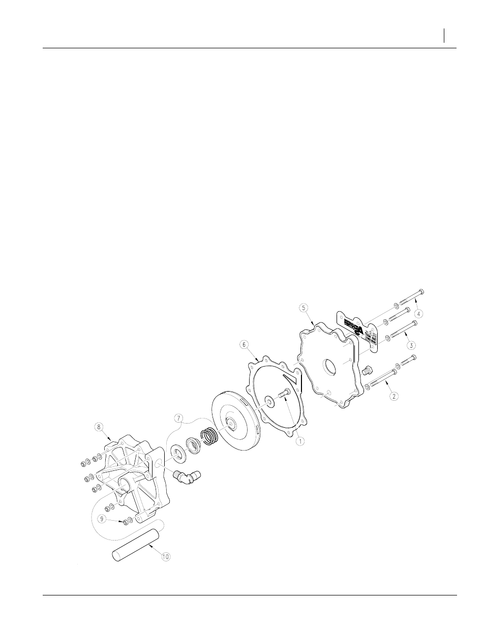
Figure 14
Centrifugal Pump Assembly
11591
3.
Clean off any grease or dirt from the pump shaft (10)
and dry the shaft so the rubber bellows on the me-
chanical seal will adhere to the shaft properly when
assembled.
4.
Bolt up the pump input bearing housing (not shown)
to the volute housing (8) using bolts (2), (3) and (4)
with spacers (not furnished) for alignment and as-
sembly of the shaft seal.
5.
Assemble the seal (7) without its spring, on the
pump shaft by pushing on the inside rubber portion
of the seal using water as the lubrication. The graph-
ite seal face should touch the white ceramic seat
face. The rubber bellows adhering to the pump shaft
should not protrude more than 1/16" beyond the
stainless steel ring located on the impeller side of
the seal.
6.
Assemble the seal’s spring and the impeller, being
careful not to move the mechanical seal that has
been positioned on the pump shaft. Torque the im-
peller bolt (1) 16 - 18 ft./lbs.
7.
Remove the three bolts and spacers. Using gun
grease, lubricate the gasket (6). Assemble the gas-
ket (6) and suction housing (5) using bolts, flat wash-
ers and locknuts. Torque nuts 16 - 18 ft./lbs.