Control box assembly {manual control – Great Plains TM700 Operator Manual User Manual
Page 24
Tractor Mount Sprayer
500-052M
5/13/2003
22
11953
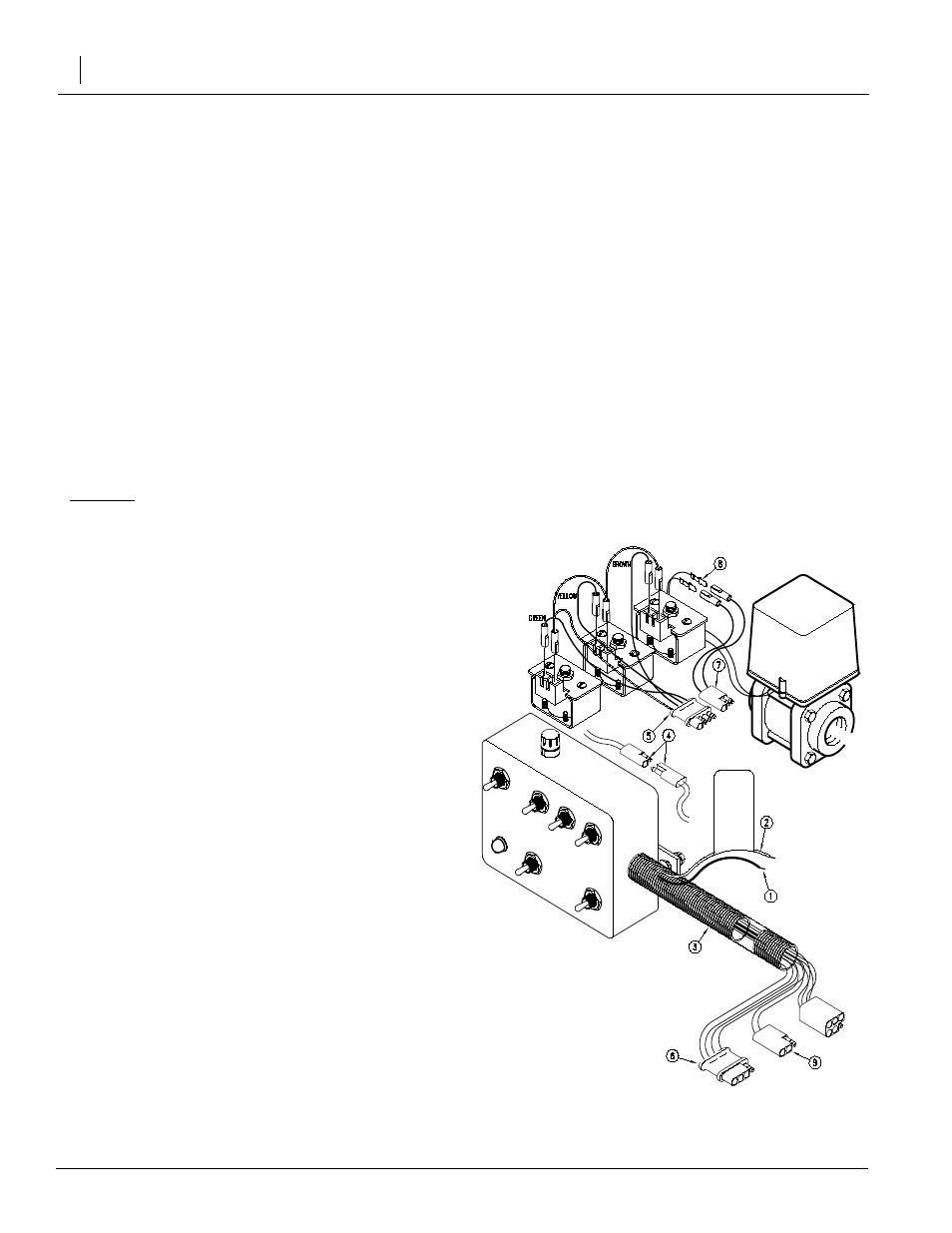
Figure 11
Control Box Assembly
Control Box Assembly {Manual Con-
trol Systems Only}
Refer to Figure 11
1.
Remove the solenoid cover to gain access to the so-
lenoid terminals.
2.
Mount the control box on your tractor. Connect the
red wire (1) to the positive terminal of the 12 volt bat-
tery and the white wire (2) to the negative terminal.
You will need to pull the red and white wires out of
the black harness (3) until there is enough wire to
reach the battery.
Note: You may want to attach the battery leads (4) to the
battery terminals and the control box power leads so that
the control box can be disconnected easily.
After the power leads (1) & (2) are hooked to the battery,
you should be able to turn on the master switch and see
the red power light come on. Turn the master switch OFF
BEFORE proceeding to the next step.
3.
Attach the electric solenoid cord (5) to the solenoids
as shown. The green wire attaches to the front sole-
noid {front being toward the hitch}. The yellow wire
attaches to the middle solenoid and the brown wire
attaches to the rear solenoid. Connect the other wire
{white} to all three solenoids.
4.
Hook up the electric solenoid cord (5) to the sole-
noid plug (6). You may need to use the extension
cord included to reach the solenoid valves more
easily. Turn the master switch on and flip the boom
section switches to see if the solenoids are operat-
ing properly. The left boom switch should operate
the front solenoid, the center boom switch should
operate the middle solenoid, and the right boom
switch should operate the rear solenoid. If the
switches don’t correspond with the correct sole-
noids, check your electric cord assembly in step 3,
or the wiring of the control box under "Control Box
Wiring Assembly Instructions" on page 23.
5.
Attach the electric ball valve cord (7) to the terminals
(8) on the electric ball valve.
6.
Hook up the electric ball valve cord (7) to the ball
valve plug (9). You may need to use the extension
cord included to reach the ball valve. Turn the mas-
ter boom switch and flip the pressure adjust switch.
The ball valve should operate when the switch is
flipped.
7.
Reassemble the solenoid cover over the top of the
solenoids.