Marker chain, Gauge-wheel drive adjustment, Disk scraper adjustment – Great Plains 2N-3010 Operator Manual User Manual
Page 36: Leveling adjustment, Marker adjustments
34
Section 3 Adjustments
2N-2410 and 2N-3010 Folding No-Till Drill 196-126M
12/27/05
Great Plains Mfg., Inc.
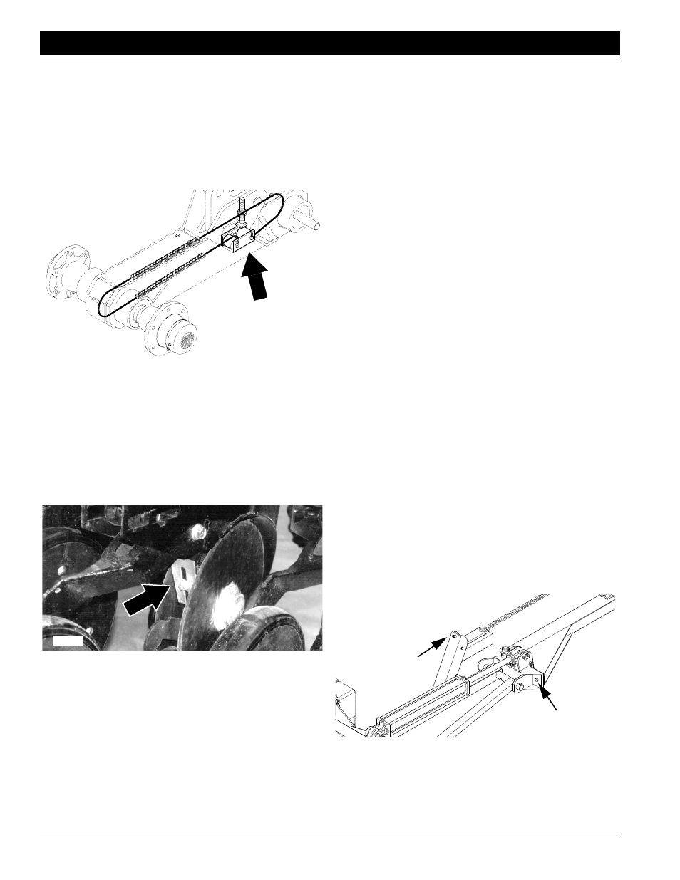
Gauge-Wheel Drive Adjustment
Inside both gauge-wheel arms are two idler sprockets as
shown in Figure 3-12. Adjust these sprockets after the first
100 acres of drill use and at the beginning of each season.
To adjust, move the front idler sprocket on the top of the
chain down by loosening the jam nut and screwing in the
adjustment stud, located on top of the wheel arm. Do not
over tighten chains, causing excessive wear. Retighten
the jam nut to maintain the idler position.
Figure 3-12
Gauge-Wheel Idler-Sprockets Adjustment
Disk Scraper Adjustment
To keep the double-disk openers turning freely, dirt scrap-
er are mounted between the disks to clean as the disks ro-
tate. As field conditions vary, you may need to adjust the
scrapers. In damp conditions, the scrapers may need to be
lowered. If openers are not turning freely, the scrapers
may need to be raised. To adjust scrapers, loosen the 3/8-
inch bolt shown in Figure 3-13 and move scraper as need-
ed.
Figure 3-13
Disk-Scraper Adjustment
NOTE: The optional Air Design® disk scrapers are self-
adjusting.
Leveling Adjustment
Equal coulter depth across the implement can only be
maintained if all frame sections are level. Periodic frame
16163
leveling should not be necessary. If your drill appears to lift
or plant unevenly, check the following before re-leveling
the drill.
First, make sure the tongue is level to the ground while
running in the field. Refer to Hitch Height Adjustment,
“Drill Preparation and Setup,” page 10.
Second, check the field-lift cylinders. Be sure they are
properly bled, operating correctly, and do not have internal
oil leaks.
If leveling is necessary, follow instructions under Frame
Leveling Adjustment, page 13.
Marker Adjustments
Marker Chain
There are two marker chain adjustments–lifting slack and
folding slack. These adjustments should be performed
during initial marker assembly, but additional adjustment
may be needed. The adjustments are interrelated and
should be made in the following order:
1.
Lifting Slack. Start with the marker in the unfolded
position. Back the full-threaded adjustment bolt down
(see Figure 3-14) until the head extends as little as
possible. Slowly fold the marker, observing the motion
of the disk. If the marker disk slides across the ground
more than about one foot before the chain and linkage
lifts it up, the chain is too slack. Tighten the chain by
moving the clevis one or two links at the inside end of
the chain. Recheck by repeating this process.
If the chain does not have enough slack when the
marker is in the unfolded field position, the chain will
prevent the end of the marker from dropping into field
depressions. Correct this condition by moving the util-
ity clevis one or two links, giving the chain more slack.
2.
Folding Slack. After the adjustments in step one have
been completed, fold the marker. The adjustment bolt
is provided to take the slack out of the chain while the
marker is in the folded position. Extend this bolt until
the slack is out of the chain. Lock the bolt in this posi-
tion by tightening the nuts on either side of the upright
channel on the first marker section.
Figure 3-14
Full-Threaded Adjustment Bolt
13008
Shear Bolt
Adjustment Bolt