Ram extension installation, In figure 3.9 using the bo – Wheatheart Self-Propelled Auger Kit (Wheatheart R Series) User Manual
Page 21
W
HEATHEART
- S
ELF
-P
ROPELLED
A
UGER
K
IT
3. A
SSEMBLY
W
HEATHEART
BH & R S
ERIES
3.8. R
AM
E
XTENSION
I
NSTALLATION
30761 R0
21
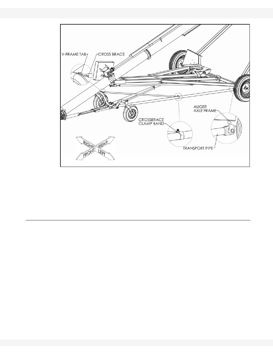
Figure 3.9 Self-Propelled Auger Frame Installation
9. One end of the crossbrace is attached to the v-frame tab, the other is
attached to the transport tube using clamp bands (Figure 3.9).
10. When attaching to the v-frame, be sure to mount one crossbrace to the top
side of the v-frame tab, and the other to the bottom.
3.8. RAM EXTENSION INSTALLATION
The ram extension slides into the a-frame attached to the tabs on the v-frame.
The ram extension length must be set at the proper distance from the ram
mounting a-frame for proper operation of the transport kit (see Figure 3.8, Table
3.1 (measurement “C”) and Figure 3.10 (measurement “C”)).