Wheatheart Self-Propelled Auger Kit (Wheatheart R Series) User Manual
Page 20
3. A
SSEMBLY
W
HEATHEART
- S
ELF
-P
ROPELLED
A
UGER
K
IT
3.7. U
NDERCARRIAGE
I
NSTALLATION
W
HEATHEART
BH & R S
ERIES
20
30761 R0
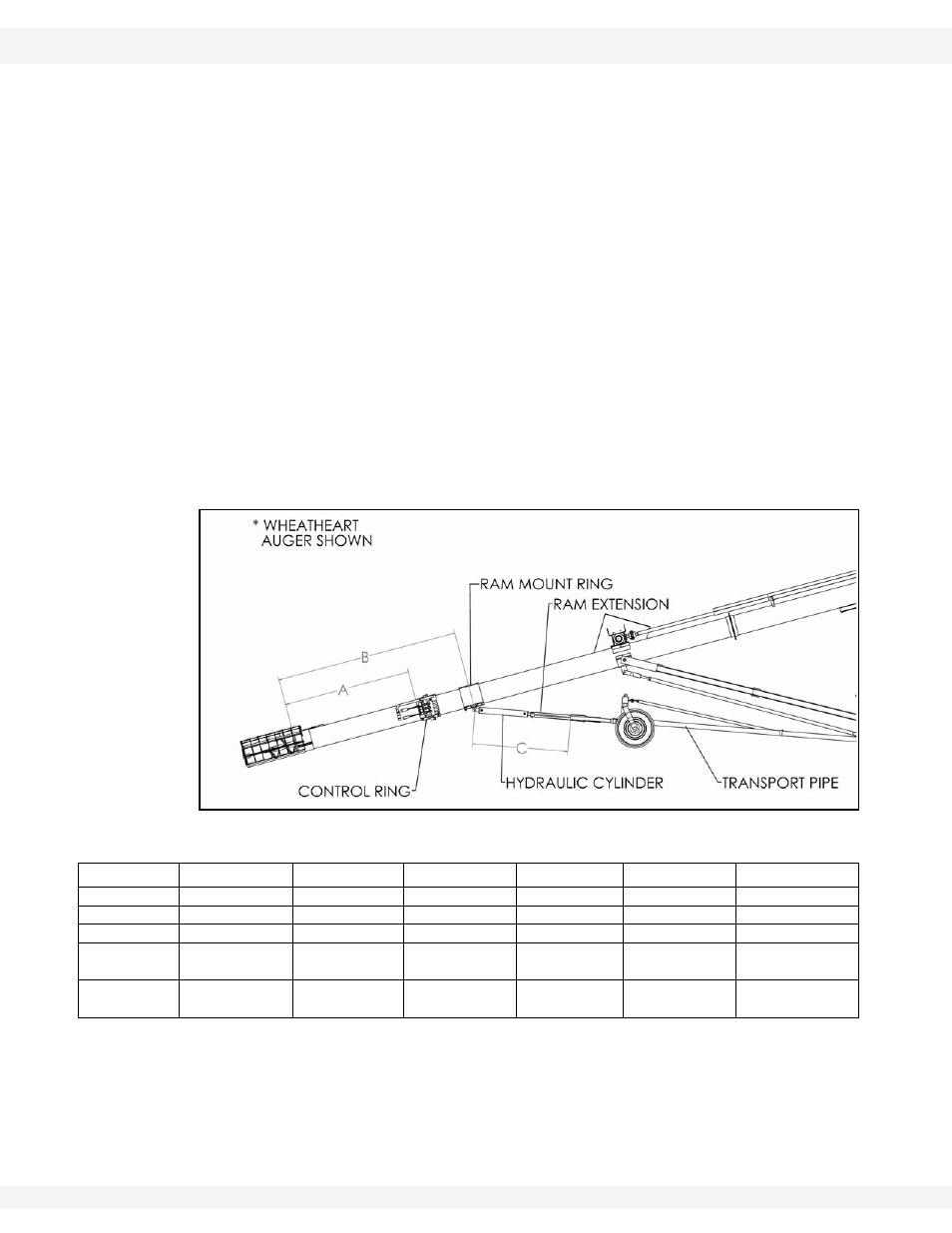
4. In the location noted in Figure 3.8, bolt the control panel ring to the auger
tube approximately to the measurements in Table 3.1. Do not tighten the
bolts yet.
Note:
The ram mount ring and the control ring normally get mounted together as one
unit. The only exception are the 46’ and 51’ auger models. For these models, two
extra tube half clamps are provided.
5. Mount the ram mount ring to the tube as indicated ahead of the control ring;
refer to Figure 3.8.
6. Connect the fully retracted cylinder to the tab on the ram mount ring and the
ram extension.
7. The ram extension slides into the a-frame attached to the tabs on the v-frame
as shown in Figure 3.10. The ram extension length must be set at the proper
distance from the ram mounting a-frame for proper operation of the transport
kit. To set the ram extension length, elevate the v-frame to adequately clear
the ground, but not interfere with the auger support arms.
8. Elevate
the
v-frame,
undercarriage pipes, and ram assembly to form a
straight line (transport position) as shown in Figure 3.8. Tighten the control
ring and ram mount ring bolts.
Figure 3.8 Control Ring Installation
Table 3.1 Recommended Transport Pipe Length
Auger
R 8 x 36
R 8 x 41
R 8 x 46
R 8 x 51
R 10 x 36
R 10 x 41
A
79”
84-1/2”
85”
92-1/2”
76-3/4”
84-1/2”
B
83”
88-1/2”
115”
123”
80-3/4”
88-1/2”
C
27-1/4”
24-1/4”
37-1/2”
43”
24”
26-3/8”
Transport
Pipe
86”
120”
120”
144”
92”
120”
Ram Exten-
sion
15”
15”
28”
28”
15”
15”