Pinion gear adjustment, Undercarriage installation, Notice – Wheatheart Self-Propelled Auger Kit (Wheatheart R Series) User Manual
Page 19
W
HEATHEART
- S
ELF
-P
ROPELLED
A
UGER
K
IT
3. A
SSEMBLY
W
HEATHEART
BH & R S
ERIES
3.6. P
INION
G
EAR
A
DJUSTMENT
30761 R0
19
3.6. PINION GEAR ADJUSTMENT
For gear depth alignment, refer to Figure 3.7.
The pinion gear should mesh with the ring gear to provide maximum tooth
contact (Figure 3.6).
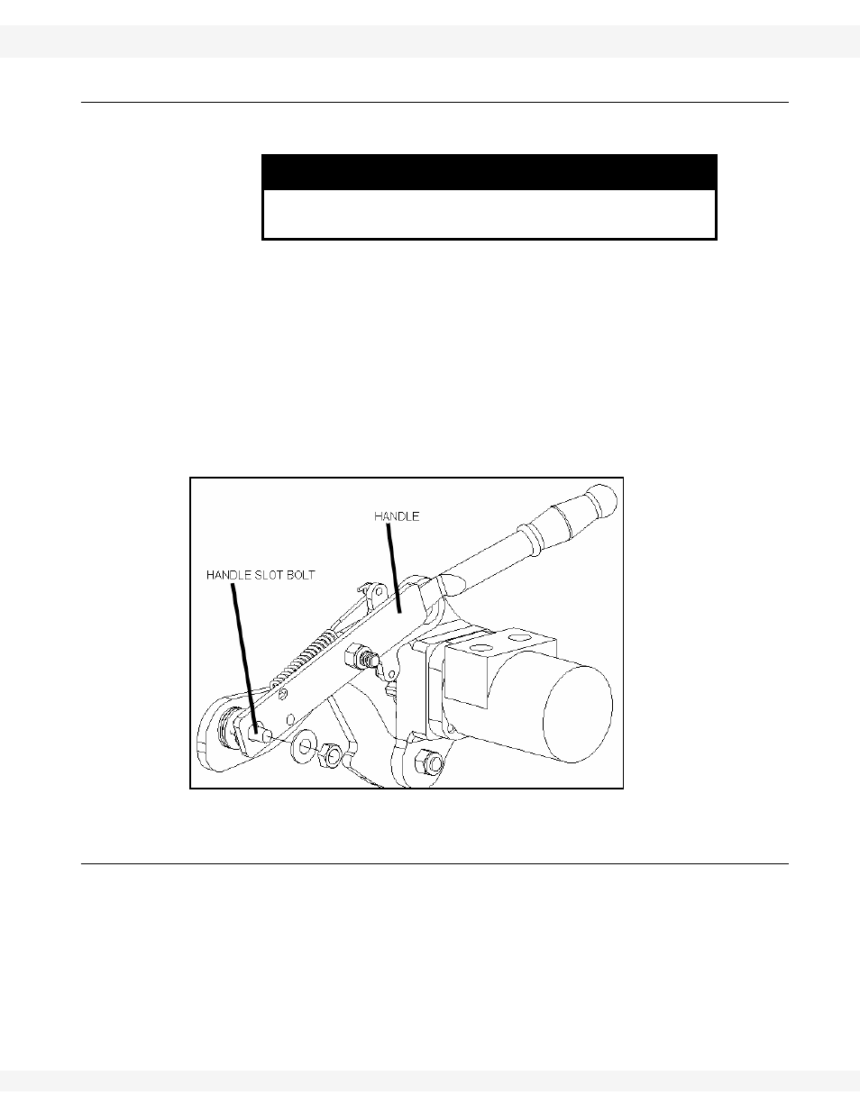
If the pinion gear does not mesh fully with the ring gear, adjust the handle slot
bolt (which bolts to the drive mount clamp) so full meshing of pinion gear is
achieved when handle is in over-center position (Figure 3.7).
Gear teeth binding: If the handle will not ‘lock’ into over-center position, loosen
the slot bolt nuts and slide the handle away from the tire.
Insufficient Meshing: If the pinion gear will barely mesh with the ring gear,
loosen the slot bolt jam nuts and slide the handle towards the tire until the pinion
gear teeth mesh with the ring gear teeth without binding.
Figure 3.7 Over-Center Assembly Adjustment
3.7. UNDERCARRIAGE INSTALLATION
Important:
Pre-Assembly: When assembling the frame pipes, ram extension, and cylinder
under the auger, the components should form a straight line from the axle to the
ram mount ring when the auger is fully lowered.
1. Lower the auger completely.
2. Attach
transport
frame
pipes to axle tabs on the auger axle frame as shown
in Figure 3.9 using the bolts and locknuts provided.
3. The clevis end of the transport pipe fits inside the clevis on the v-frame.
Attach using the bolts and locknuts provided.
NOTICE
Failure to ensure proper gear meshing will result in gear
damage.